Continue to Site

Welcome to EDAboard.com

Welcome to our site! EDAboard.com is an international Electronics Discussion Forum focused on EDA software, circuits, schematics, books, theory, papers, asic, pld, 8051, DSP, Network, RF, Analog Design, PCB, Service Manuals... and a whole lot more! To participate you need to register. Registration is free. Click here to register now.

Pre amplifier with feed back query

Status
Not open for further replies.

goldsmith

Advanced Member level 6
Joined
Dec 14, 2010
Messages
3,981
Helped
741
Reputation
1,486
Reaction score
726
Trophy points
1,413
Location
Tehran - IRAN
Activity points
24,546
Hi My friends!
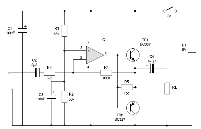
I designed a pri amplifier with Tl072(as you can see at below figure)
But when i cut the bias diodes of complementary stage, and when i connected the feedback loop of opamp (to the out put of complementary) for secure the bias voltages of complementary i thought that the output will be without crossover distortion . but again i saw the cross over distortion in output. where is the problem? pr.JPG
Thanks in advance
Goldsmith
 

Cross over distortion is caused by the output circuit not having enough bias on it and the output devices not having enough current through them. So connect your NFB loop to the DC output of the output pair. The circuit should stabilize with this point at exactly 1/2 of the supply line voltage and the output devices should be running at least 5mA of current - some high power designs run 60mA. Put in a high level sinewave and ensure that it is clipped equally on its +ve ans - ve half cycles, this should ensure that the driver circuits are symmetrical. Also check the circuit at low and high audio frequencies to ensure that you are not running out of loop gain and not getting the benefit of the NFB to clean things up.
Frank
 

Dear Frank
Hi
Thanks for your reply.
When i used a buffer circuit with opamp in my feedback loop again i saw that problem. i confused. what should i do?
Appreciate
Goldsmith
 

What is the purpose of the first op-amp??
And why you use only three diodes to bias the output stage ?? Darlington output stage need four diodes to proper bias, or instead of the diodes you could use Vbe multiplier. And also you need to add emitter resistor to the output stage.
And to reduce crossover distortion apply negative feedback to the output stage.


Jony130 has got it about right with the first circuit. For max output power the DC output level (junction of C1 and transistors) should be 1/2 Vcc. To get this each pair of transistors should conduct the same current to get into this region, two Vbes have to be compensated for - put another diode in series with D2. This should make the currents equal but as I said it might not be high enough to ensure both output transistors are switched on enough to provide current gain. You could try and put a 1K potentiometer strapped as variable resistor in series with D7 and D6. as its resistance increases you should be increasing the current in the output transistors. NB make sure you start off with it set to zero ohms else the output transistors might try and take 2 Amps and rapidly overheat.
The second circuit from Jony130 is not to be recommended as it relies totally on the NFB to cure the distortion as there is zero current in the output transistors without any input signal.
Frank
 

Dear jony130
Hi
You should know that the op amp as a amplifier should has dual supply (simultaneous ) . and your circuit has many problem but thanks for your attention.
Goldsmith

---------- Post added at 15:03 ---------- Previous post was at 14:35 ----------

Dear chuckey
Hi
Thanks for your reply.
The cause of 3 diode for my transistors is this: the Transistors will bias as high as , when i put 4 diode in parallel with the BE junctions. you are right , if i use diode with transistor! my mean is that when i use transistor as a diode , i have to use 4 transistor as diode , in parallel with BE junctions!. but potential of 3 1n4148 diode is enough for driving 4 transistor.
But I wanna compensate the BE potentials with feed back loop. how can i do it? is it possible that you guide me please?
Thanks in advance
Goldsmith
 

Dear jony130
Hi
You should know that the op amp as a amplifier should has dual supply (simultaneous ) . and your circuit has many problem but thanks for your attention.

This is not the truth, op-amp can also work with single supply power supply.
https://www.edaboard.com/threads/130437/#post569417

The cause of 3 diode for my transistors is this: the Transistors will bias as high as , when i put 4 diode in parallel with the BE junctions. you are right , if i use diode with transistor! my mean is that when i use transistor as a diode , i have to use 4 transistor as diode , in parallel with BE junctions!. but potential of 3 1n4148 diode is enough for driving 4 transistor.
In practical circuits we use Vbe multiplier (Q1) + additional Re resistors in the push-pull amplifier

66_1320685817.png


https://www2.engr.arizona.edu/~brew/ece304spr07/Pdf/VBE Design.pdf

The second circuit from Jony130 is not to be recommended as it relies totally on the NFB to cure the distortion as there is zero current in the output transistors without any input signal.
Frank
Well I add R5 resistor, who helps eliminate crossover distortion. But you right this is not so good circuit despite this additional resistor (R5).
 
Last edited:

Dear Jony
Hi
When you need a simultaneous sinusoidal wave , you have to use dual supply. i know that the op amp can work with single supply as well as , but when you wanna amplify a signal , we should put dual supply.
And about your second circuit for BE biasing. its real name is parallel regulator. i know about that but i want to compensate the BE voltage with feed back loop of op amp.
Though Thanks for your reply.
Best Regards
Goldsmith

---------- Post added at 00:21 ---------- Previous post was at 00:17 ----------

Is it possible that you say the reason of using R5 in your circuit(100 ohm), please? Thanks in advance
 

Dear Jony
Hi
When you need a simultaneous sinusoidal wave , you have to use dual supply.
What?
This circuit will work as AC signal amplifier. The only restriction is that the signal frequency must be greater than:
F = 0.16/ (C2 * R3) = 10Hz or F = 0.16/(C4 * RL)


And about your second circuit for BE biasing. its real name is parallel regulator. i know about that but i want to compensate the BE voltage with feed back loop of op amp.
In amplifier circuit we coll it Vbe multiplier becaues as the name suggest this circuit not only multiplies Vbe voltages but this circuit also multiplies the temperature coefficient what is also very important in the power amplifier design.
The feedback loop in not enough to "compensate the BE voltage". And that is why almost one hundred percentage of real amplifiers have additional bias circuit in the form of a Vbe multiplier.
Is it possible that you say the reason of using R5 in your circuit(100 ohm), please? Thanks in advance
Reducing the crossover distortion by providing additional paths for the load current, and further this additional current bias the output stage.
 

Dear Jony
Hi
See here please:
amp1.JPG
amp2.JPG
When you need a complete and good sine wave , you will need simultaneous supply.
Best wishes
Goldsmith
 

Every real life "active device" to work properly as an amplifier supplied from a single source need proper bias circuit.
When you use BJT as a CE amplifier, you use a voltage divider to bias the active device somewhere in the "linear region".
In case of single supply op amp you have to do the same think. You need to bias the op amp somewhere in the middle of his "linear region".
And you also need to add the coupling capacitors.

See the example circuit

96_1320874827.png


Voltage divider (R1 and R2) provide bias voltage (virtual ground) to non-inverter input.
Rf and R3 set the AC voltage gain.
Cin and Cout - coupling capacitors
C1 - bypass capacitor
R4 - pull down resistor.

Do you finally understand this topic ?
 
Dear Jony
Hi
Thanks for your guidance . your right . when i simulated your suggestion circuit , obtained thing that you said as well as . Thanks very much for this good circuit.
Best Regards
Goldsmith
 

Status
Not open for further replies.

Part and Inventory Search

Welcome to EDABoard.com

Sponsor

Back
Top