Continue to Site

Welcome to EDAboard.com

Welcome to our site! EDAboard.com is an international Electronics Discussion Forum focused on EDA software, circuits, schematics, books, theory, papers, asic, pld, 8051, DSP, Network, RF, Analog Design, PCB, Service Manuals... and a whole lot more! To participate you need to register. Registration is free. Click here to register now.

Which select transistors? I need high dB gain

Status
Not open for further replies.

micman

Member level 1
Joined
Mar 27, 2002
Messages
40
Helped
0
Reputation
0
Reaction score
0
Trophy points
1,286
Activity points
207
Hi,
I want amplify the signal on buffer(VCO) -5 dbm
I want find a transistor NPN with high dB gain. I'd like to find a NPN to gain > 20dB

Have you a name of transistor for small signal to recommend?

PS: Frequency operation is less 250Mhz
 

A MMIC would be your best bet say a ERA-5 or a MAR-6 They both have 20 + dB gain at 100MHz.
But for stability I would suggest that you consider using 2 of them and keeping the gain in each to ~ 10 - 12 dB.
if you drive any device too hard it will go into compression and start to distort the signal.
It is ALWAYS wise to do hi gain in stages :)

cheers
Dave
 

I'd agree with davenn. There are multiple sources of MMIC on the web.
 

What's your IP1dB? I think you can select one MMIC to do so, because multi-stages may cause unstable.
 

As far as I undestood gain>20 then Pout > 20-5 = 15 dBm.
In this case MAR-6 is not suitable since P1dB = 3 dBm

Have you got any requirement about isolation and noise figure ?
 

What's your IP1dB? I think you can select one MMIC to do so, because multi-stages may cause unstable.

Tony

Hi gain in a single devide is likely to be more unstable
hence my comments in my first post :)

Dave
 

thanks guys for all these answers!!

I'm newbie in ameteur radio. I like this and I like experiment!.
Now I have buy MAR-6 and MAR-8, I want to try and do some testing.

I have a BF199 but in datasheet there is not written db gain! Why? You know how much gain this transistor?
 

I did experiment with BF199, this schematic of my VCO 170Mhz + buffer + ampli
The result is +14dBm !!
with BF199 I have 19dBm !

vco.png
 

very good, well done :) what project is this VCO going to be the basis of ?
the data sheet gives a DC current gain

and btw welcome to the world of amateur radio !!
I have been playing on the ham bands for 30 years now. I do a lot of equip construction particularly in the microwave bands 1GHz to 47GHz
I am by no means an expert and there are areas where my electronics theory lacks a bit. But i make up for it by just getting out there and experimenting and making things work.

forums like this one are great for asking questions, and often just for sitting back and reading, its amazing what you can learn :)

cheers
Dave
 

Hi davenn, thanks for reply!

I read that you use the SHF bands WOW!!, I'm not even imaginable for me. I try use VHF because is "more simple" for experiment with newbie.
The goal are:
-Build a radio TX(1W) trasmit DTMF tone
-Build a radio RX(with motorola MC3362) recive DTMF tone
-Build a yagi antenna
-Build power amp 20W and try trasmit long distance a DTMF tone at 110Km
 

Hi Saeedbayanlou

welcome to the forums :)

As I said to micman.... sit back relax and learn lots :)

@ micman ok cool ... but you do realise there is no ham band at 170MHz ? the closest ham band to there is the 144- 148 with slight variations depending on country you are in ( some only have 144-146MHz)
you dont want to transmitting on 170MHz, else the authorities in your country wont be very happy with you.

144MHz up to a few watts is reasonably easy to achieve with only reasonable adherence to construction techniques. 10W -> 20W and more requires some more dedicated though on circuit board layout.
Some easy ways to generate that sort of power level is by the use of Motorola power block modules like the RA08H1317M that does 8Watts across the 2m band (144MHz) or the RA30H1317M that does 30Watts across the same band. These are great modules as little as 50-100mW will give their full power out ...
Do a google search for the datasheets on those 2 devices :)

What country are you in micman ?

cheers
Dave
VK2TDN <--- my amateur radio callsign
 
Last edited:

Hi davenn, you're right I was wrong, I mean 144MHz.
A question, In this wavelength (2m) , How is the propagation? for a link of 110/130 Km , TX and RX must have the free field ? These waves can bounce off?

my country is italy (sorry for my english)
 

over that distance, and under normal propagation conditions, it would have to be a relatively clear pretty much line of sight path

the 2 main exceptions.....

1) aircraft reflection is a popular mode for working non-line of sight paths. out to an easy 1000km but contacts are usually very brief, when the aircraft is roughly 1/2 way between the 2 stations. The guys these days mainly use digital modes to get lots of data through quickly in each direction. SSB cab be used but much slower in voice mode.

2) the other common mode used and particularly during the summer months is tropospheric ducting
there's 2 forms of that.....
a) ... low level ducting mainly along coast lines, where layering of warm and cool layers of air can form ducts that act much like a waveguide does on the microwave bands, a signal can enter the duct and travel 100, 500, 1000 or so km and pop out the other end with very little attenuation. its good for at least 50MHz through to at least 1296MHz

b) ... higher level tropo ducting that is associated with large high pressure weather systems. These can provide really excellent signal levels over paths exceeding 3000km.

in my part of the world ( where I have personal experience ) that long haul ducting provides paths between Australia and New Zealand on 144MHz, 432MHz and occassionally 1296MHz.
I have worked between NZ and Australia probably 20 times at least over the last 30 years.
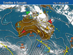
here's a weather synoptic map for conditions during one very strong opening....

click on the image to see full size :)
090101 Synoptic huge 2m opening to ZL.jpg

There's a high pressure centre to the right edge of the image, over nthrn New Zealand. You can see that there are isobar lines running between the eastern Australia coast and across to NZ.

I know this is all far from your original topic.... sorry... but with your amateur radio, I hope you and maybe others find it interesting :)

cheers
Dave

PS your english is pretty good :)
 
Last edited:

Status
Not open for further replies.

Part and Inventory Search

Welcome to EDABoard.com

Sponsor

Back
Top