Welcome to our site! EDAboard.com is an international Electronics Discussion Forum focused on EDA software, circuits, schematics, books, theory, papers, asic, pld, 8051, DSP, Network, RF, Analog Design, PCB, Service Manuals... and a whole lot more! To participate you need to register. Registration is free. Click here to register now.
Well i get to know that Floquet's Ports can be assigned by using unit cell boundaries. I tried it as it defines the Zmin and Zmax for the whole structure i.e in X and Y (Unit cell boundaries) and in Z (Open).
I tried it with a multilayer reflectarray antenna inorder to match my results with some paper but still i'm not able to achieve them.
I am trying with different boundary conditions but still unable to achieve the desired results, m not sure what will be exact boundary conditions in this case.
As far as I remember you can only use Floquet ports in CST with frequency domain solvers, not the transient solver. You can use Floquet ports to design your unit cell. It is not suitable for full antenna simulation.
What are you simulating, the whole array, or the unit cell (i.e. one of those repetitive small periodic patches)?
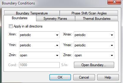
If it's the whole array, use open boundary conditions everywhere, if it is unit cell, use periodic boundary conditions. I don't think you are simulating the whole array.
You can only use Floquet ports for unit cell simulation. But finite antenna simualtion, and unit cell simulations are totally different things. Unit cell simulations can help you to understand the behavior, but for finite size array (you cannot realize an infinite array) you have to see the truncation effects, and maybe further optimize some dimensions to finalize your design.
---------- Post added at 22:25 ---------- Previous post was at 22:24 ----------
Also you cannot just try different boundary conditions. It has to have a physical meaning.
Use Floquet ports. I only have transient solver license, and you can set floquet ports in frequency domain solver. But there must be a place to decide number of modes included. Put a somewhat small number first (you may put even numbers, to include equal number of TE and TM modes). Then you can increase and compare the changes in your result, if you don't see significant changes as you increase the number of modes, it means you have included enough modes. You can truncate both +z and -z with Floquet ports if you like.
---------- Post added at 22:51 ---------- Previous post was at 22:37 ----------
Can you give your reference name? It may be more useful if I look at the paper.
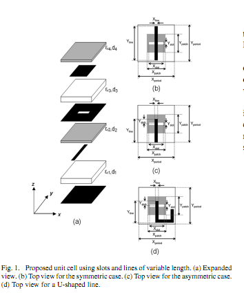
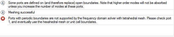
I tried but in case of floquet port it gives an error that " Zmin and Zmax is not homogeneous". Here is the paper title "Reflectarray Element Based on Aperture-Coupled Patches With Slots and Lines of Variable Length". I am trying to verify the symmetric case. Take a look at it and let me know what will be the possible solution to get the results matched with the paper results.
I had a look at the paper. So, stick to Floquet ports. The error your are getting usually happens when two or more dielectric is touching to a radiating surface, in this Zmin and Zmax. I don't see a reason why this should be the case for your geometry, so double check your model. Do you have anything placed on top of top dielectric surface (any vacuum box etc.)? If not, you may place a Vacuum Box to top and bottom to move your "Open" boundaries away from your dielectric substrate.
Another suggestion is to change "Open" radiating boundaries to "Open (add space)" boundaries. Because, if Open is chosen CST places PML to match the material touching to surface (as if those surfaces are extending to infinity), with "Open (add space)" it matches PML to Vacuum, so an infinite free space behavior is simulated.
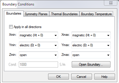
There are two cases, one with the ground plane at the bottom. For the case with ground plane, you don't have to put any port to bottom, just assign Et = 0 boundary condition on that surface (i.e. right at the level where the ground plane is, you can adjust it with first putting a Vacuum box, and playing with height of it).
Thank you so much for your time and checking the model design. I will simulate again keeping in mind your suggestions and will let you know about the progress. I wish this time i get the desired results.
One last thing. If you are trying to regenerate the phase plots (vs. changing lengths), don't get fooled by the absolute numbers, phase is most of the time relative, it may be different for different excitation locations. The initial numbers may be off, but the shape and slope should be the same (i.e the difference between smallest length's phase and the highest length's phase should be the same, the curve shape should be the same, but everything may be shifted down or up by some certain amount of phase)
---------- Post added at 21:33 ---------- Previous post was at 21:30 ----------
By using unit cell boundary conditions the phase plots show an identical shape but values are different for different lengths. But again in that case i was not getting the results for ground plane. What i'm doing is shifting the ground plane by multiplying 0.1 with the value of Lambda and then shifting ground to that value.
---------- Post added at 04:39 ---------- Previous post was at 04:37 ----------
Where did you get lambda/10 distance? Because on the second page, under "radiating element" section, it says "An optional ground plane separated lambda/4 from the structure, eliminates the leakage of energy to the back of the antenna."
Now, I see that in the figures, they also have a case with 0.1lambda
This site uses cookies to help personalise content, tailor your experience and to keep you logged in if you register.
By continuing to use this site, you are consenting to our use of cookies.
")