Vermes
Advanced Member level 4
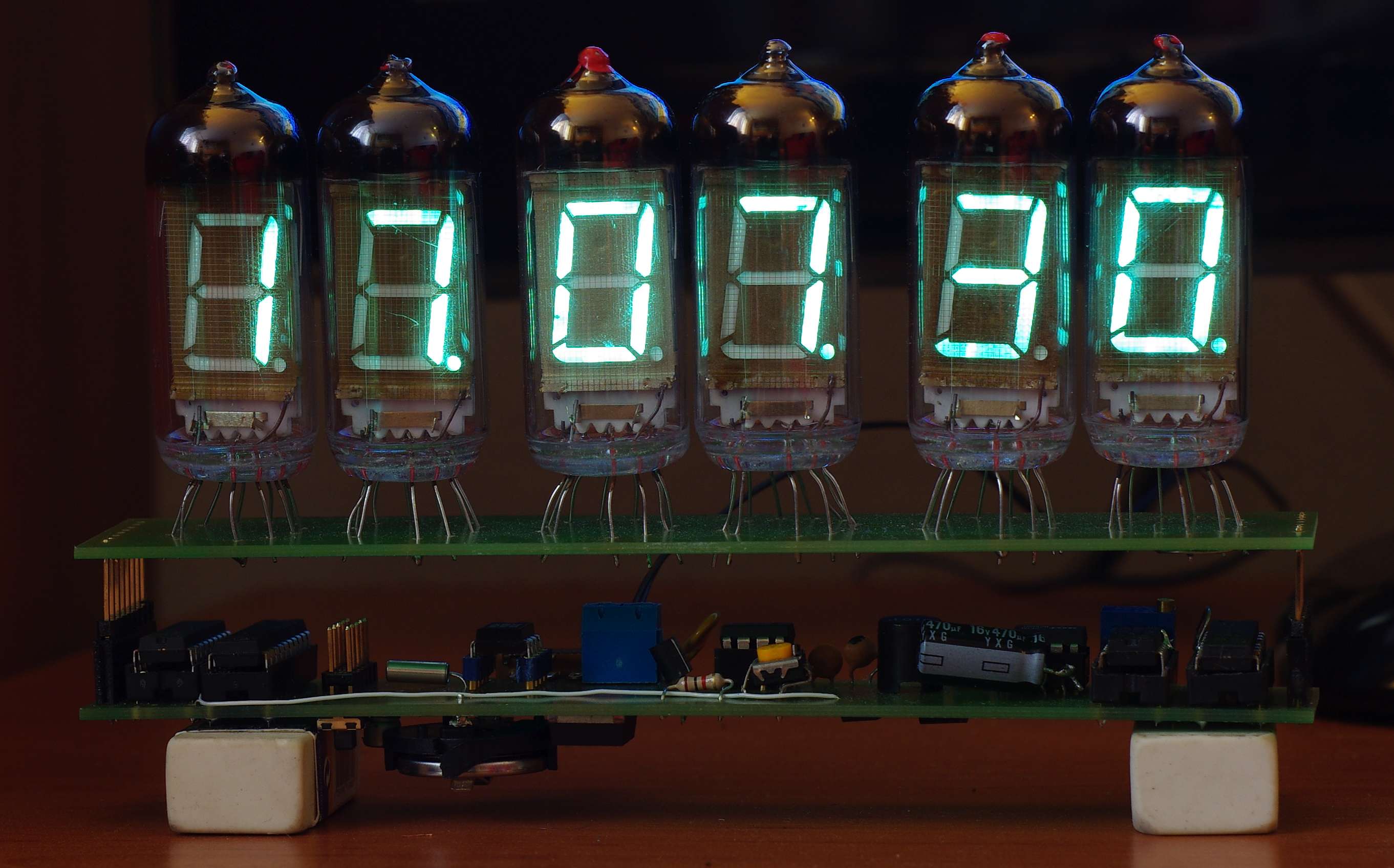
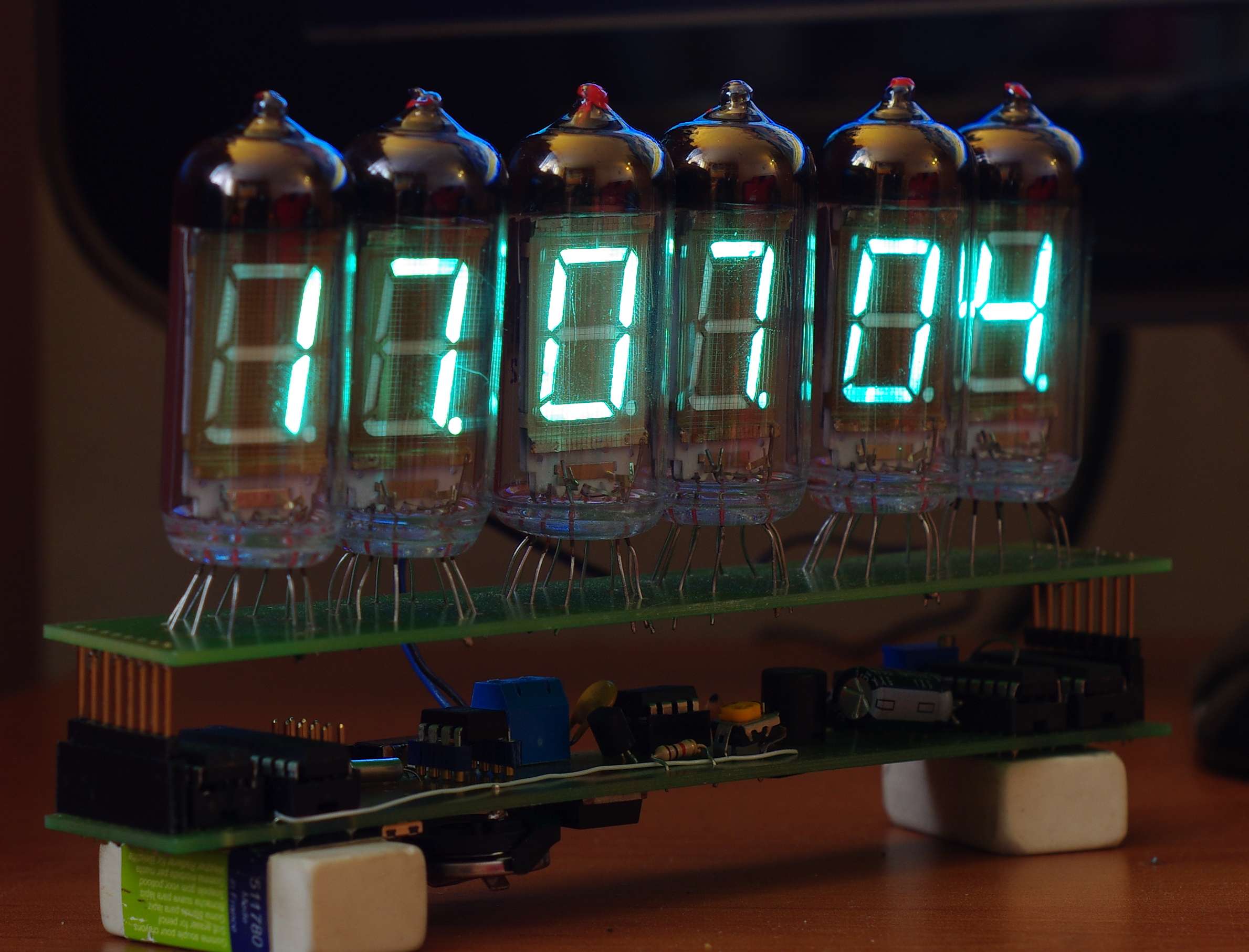
It is a tube clock on IW-11 lamps. The lamps are quite big and cheap, a character has more than 2cm in height.
Construction
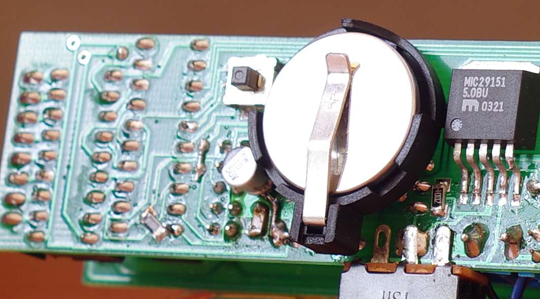
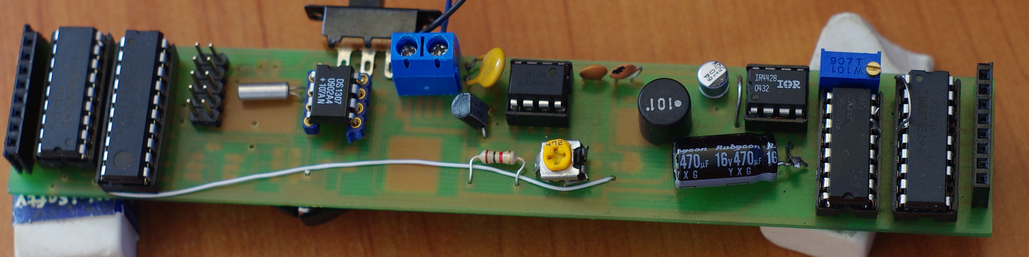
The clock is made on microcontroller Attiny2313. Also DS1307 with quartz and battery CR2032. Along digital circuits there is also 4028, which is used to choose the lamp.
The lamps are powered by about 48V. This voltage is given by converter NE555 used with Nixie watches. It is slightly modified – the degree of feedback was converted so that the voltage range was approximately 35-70V. Thank to that, a smaller transistor can be used. It is IRF7474 in SMD SO8 housing. It works properly and slightly warms up. It has smaller Rdson than often used IRFs 640/740.
Both the segments and the nets are controlled by UDN2981 buffers. They withstand up to 50V, hence the supply voltage such. The segments are directly powered by microcontroller and the nets are powered by CD4028. Input D is permanently shorted to ground. Glow is implemented by serial connection of all fibers. This arrangement threatens to uneven brightness, when the power is DC. IR4428 can be a solution for this. It is a driver for MOS transistors. It has 2 digital inputs A and B, one of them is negated. It also has 2 outputs controlled by the inputs. Thanks to that the inputs are negated relative to each other, the whole can be controlled by a single signal. Specifying the same state on both inputs would result in shorting a single output to ground, and the second to power. There are connected in series cathodes plugged in between the outputs. The system is powered by 12V DC, which is also given to the inverter. IR4428 circuit input is connected to the DS1307.
Dallas RTC system has an output pin, which generates a square wave signal of adjustable: 1Hz, 4/8/32kHz. And this signal generates a variable process of glow. 32kHz was chosen in this device. Unfortunately, the lower frequency results in acoustic effects (lights squeak). IR4428 system according to the catalog, has to withstand 1,5A. In this device, there is about 100mA. The voltage drop is large, because it is about 3V, the tension should be additionally adjusted. For sure, it is still a potentiometer 100R 0,5W for fine tuning.
The clock is set a little unusual, by the joystick for Sony Ericcson – a lot of that can be inexpensively purchased at auctions. In this project, pressing and direction (up/down) are used.
The clock is protected by reusable fuse 1A, it has a circuit breaker. It dims between 11p.m. and 6a.m. Besides, it only indicates the time. It fits on two double sided plates dimensions of 16cmx3cm. More features would not fit – only about 20% of free flash remained.
Link to original thread (useful attachment) – Zegar lampowy VFD na lampkach IW-11