Continue to Site

Welcome to EDAboard.com

Welcome to our site! EDAboard.com is an international Electronics Discussion Forum focused on EDA software, circuits, schematics, books, theory, papers, asic, pld, 8051, DSP, Network, RF, Analog Design, PCB, Service Manuals... and a whole lot more! To participate you need to register. Registration is free. Click here to register now.

How to detect AC line voltage?

Status
Not open for further replies.

sean415

Newbie level 6
Joined
Sep 22, 2008
Messages
11
Helped
1
Reputation
2
Reaction score
1
Trophy points
1,283
Activity points
1,386
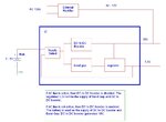
Hi, I am beginner of AC power. I am designing an IC that has a AC (120V or 220V) detect function. If AC line is active then the IC will regulate it down to 3.3V and this 3.3V will be the power supply for a micro-controller. If AC is not active, then the IC will use a 3V battery and then create a regulated 3.3V for the micro-controller.

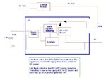
Experts please help me on this. How to sense the AC line voltage?

Thanks

Sean
 

if your requirement is to use the regulator supply whenevr ac is available and use the battery power when ac is not available,

you can use one diode to achieve what you want.
 

You can do this simple with diode. Here is example:

Circuit Ver 1.1 - Optocoupler, rele-led 12V, standard 7seg display.jpg

This is just sensing of 220V with optocoupler if You need this in future :
c_507_phonecontroller_sens_pic.jpg
 
  • Like
Reactions: ggmssr

    ggmssr

    Points: 2
    Helpful Answer Positive Rating
Sorry I did not clearly tell what I need. See attached diagram. The IC under design is within the blue box.There is a external AC rectifier that can generate 10 - 12V DC from AC.

If AC is active, then regulated 3.3V will be the supply of Band Gap and DC to DC booster.

If AC is not active, then battery is used and DC to DC booster is enabled.

How to use a diode to implement this?
 

Attachments

  • ac_det.JPG
    ac_det.JPG
    70.3 KB · Views: 99

If AC present - DC/DC is Off and regulator will supply with 3.3V "DC/DC" and "Bang Gap" ??? What is purpose of this? Design not good. Consider that diode have 0,7V drop voltage.


This is just block diagram its dificult on this diagram to make something, put circuit, and will see.
Based on this block diagram, regulator also must distinguish between 10V and 3,3V supply.
 

Attachments

  • new.jpg
    new.jpg
    101.7 KB · Views: 81
Last edited:
  • Like
Reactions: ggmssr

    ggmssr

    Points: 2
    Helpful Answer Positive Rating
tpetar,

Sorry I did not mention. The purpose is to make the IC work in both AC only and 3V battery only condition. The requirement is to let IC generate regulated 3.3V for microcontroller. 10V (not regulated) is also needed for other use.

So the challenge here is to make it work in both 3V only and AC only. I don't want to make two separate circuits for these two conditions. They should share the same circuits.

In AC only condition, DC to DC booster is not needed because the voltage is already at 10V level. The regulator needs to be powered by the 10V not the 3V battery, because the battery voltage 3V is less than 3.3V. Band gap should be also powered by 3.3V.

In battery only condition, DC to DC is needed , and all the circuits can be powered by the battery, except the regulator because of the reason I mentioned above.

Thanks

Sean


If You better look at my first illustration this is familiar situation.
Also consider voltage drop of 0,7V for diode before regulator.

1.jpg2.jpg

Check this redesign, this is ok :

new.jpg
 
Last edited:

I see what you mean. But in either case, the regulator needs the band bap voltage as a reference. In AC only condition, what is the supply of band gap circuit?
 

In only "AC" condition You get 3,3V from regulator, You can even disconnect battery and DC/DC booster, there will be 3,3V supplyed from "AC". Regulator dont need reference voltage its alone very complicated IC (Of course I must see circuit to tell more precise).
If there is no "AC" line then battery automaticly put power over DC/DC booster to regulator, ehwn "AC" line is back than then "AC" put current into regulator. My suggestion is to adjust DC/DC lower then voltage on "AC" line.

And also dont see purpose of "Supply select" perhaps something like MAX690 or familiar IC.
 
Last edited:
  • Like
Reactions: ggmssr

    ggmssr

    Points: 2
    Helpful Answer Positive Rating
You missed the point.

Here the regulator is inside the IC I am designing. It is all internal. To design a regulator, a reference (such as band gap) is needed.
 

"Supply select" selects the supply for the band gap and DC/DC.

In AC only, the "supply select" selects the regulated 3.3V as the supply for the band gap and DC/DC (although in this case DC/DC is not needed).

In battery only, "supply select" selects the battery voltage as the supply for the band gap and DC/DC.

So you see the situation. On one hand, the regulator needs band gap to create the 3.3V. On the other hand, the band gap needs the regulator output (3.3V) as the supply.

Is it called a "bootstrap" circuit?
 

Status
Not open for further replies.

Part and Inventory Search

Welcome to EDABoard.com

Sponsor

Back
Top