Welcome to our site! EDAboard.com is an international Electronics Discussion Forum focused on EDA software, circuits, schematics, books, theory, papers, asic, pld, 8051, DSP, Network, RF, Analog Design, PCB, Service Manuals... and a whole lot more! To participate you need to register. Registration is free. Click here to register now.
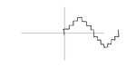
is it possible to generate wave forms other than square waves using microcontroller. Actually i wanted to generate the wave form shown in the figure. but cant figure out how to do so. Kindly help !!
Yes, if your microcontroller has an analog output port, then you can directly write the value to that port. If not, you could use a D/A (digital to analog) converter chip, also called DAC's. These can be one of several interfaces; commonly serial, parallel, I2C, etc. National Semiconductor carries a lot of parts, so start with their selection, **broken link removed**. I'd recommend going with a 1-channel, kSPS device, 8 or 10-bit part.
With a DAC, you could actually output a pretty smooth sinewave, since 8-bits would give you 256 steps from minimum to maximum. Generally, a stepped sinewave is generated by high-power, low-frequency hardware such as switching multiple DC stages to form a "rough" sinewave that can supply a LOT of current to some load.
thank you for uploading the materials but i am working with 8051 . Can you help me with that . Can you tell me the interface circuit for the 8051 to DAC .
thank you for uploading the materials but i am working with 8051 . Can you help me with that . Can you tell me the interface circuit for the 8051 to DAC .
Pick a device, look at the datasheet and at the application notes from the manufacturer. Since you seem to be a novice electronics designer, I'd start with a parallel input, if you can find one. To feed data to the DAC you set your 8/10/12 digital lines to represent the number, then "clock" a strobe line. The strobe/clock line tells the DAC to load the bits on the digital lines. Wait a defined period of time, load the next binary value onto your digital lines, strobe, and repeat, repeat, repeat. A serial connection is similar, but you have to load one bit, clock it, load the 2nd bit, clock it, load the 3rd bit...... then after the last bit, you start all over again. There are also more complex timing constraints to be aware of in a serial data transfer.
thank you for uploading the materials but i am working with 8051 . Can you help me with that . Can you tell me the interface circuit for the 8051 to DAC .
If the frequency of the output waveform is relatively low, you may like to generate it directly by pulse width modulation (PWM). This method needs a lowpass filter after the MCU pin.
The output reference voltage will be about Vcc/2, that is about 2.5V
This site uses cookies to help personalise content, tailor your experience and to keep you logged in if you register.
By continuing to use this site, you are consenting to our use of cookies.