Continue to Site

Welcome to EDAboard.com

Welcome to our site! EDAboard.com is an international Electronics Discussion Forum focused on EDA software, circuits, schematics, books, theory, papers, asic, pld, 8051, DSP, Network, RF, Analog Design, PCB, Service Manuals... and a whole lot more! To participate you need to register. Registration is free. Click here to register now.

[SOLVED] Oscilloscope Tenma 72-6800 no trace

Status
Not open for further replies.

whitspirit

Newbie level 5
Joined
Oct 20, 2011
Messages
8
Helped
0
Reputation
0
Reaction score
0
Trophy points
1,281
Activity points
1,373
Hello.

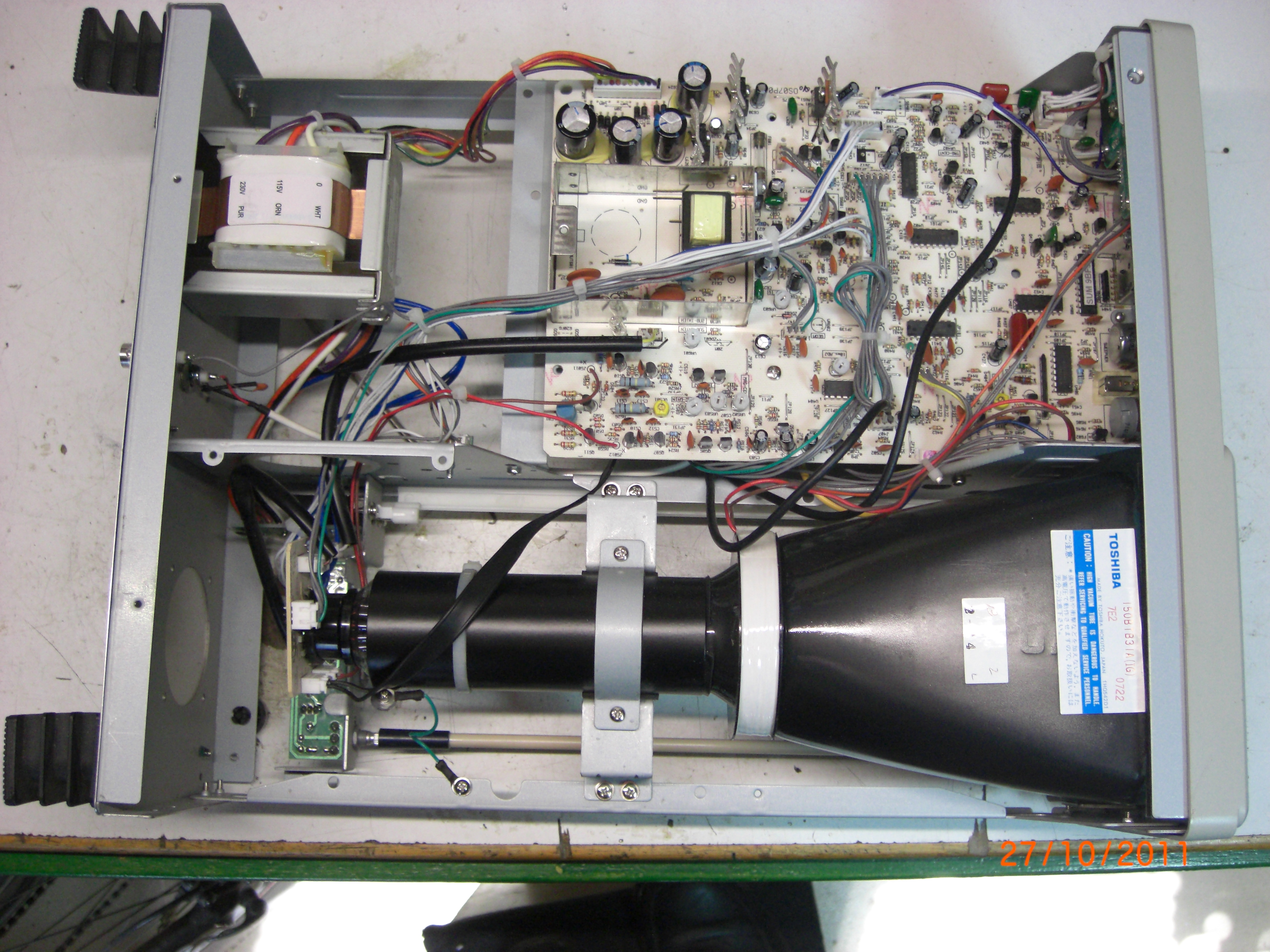
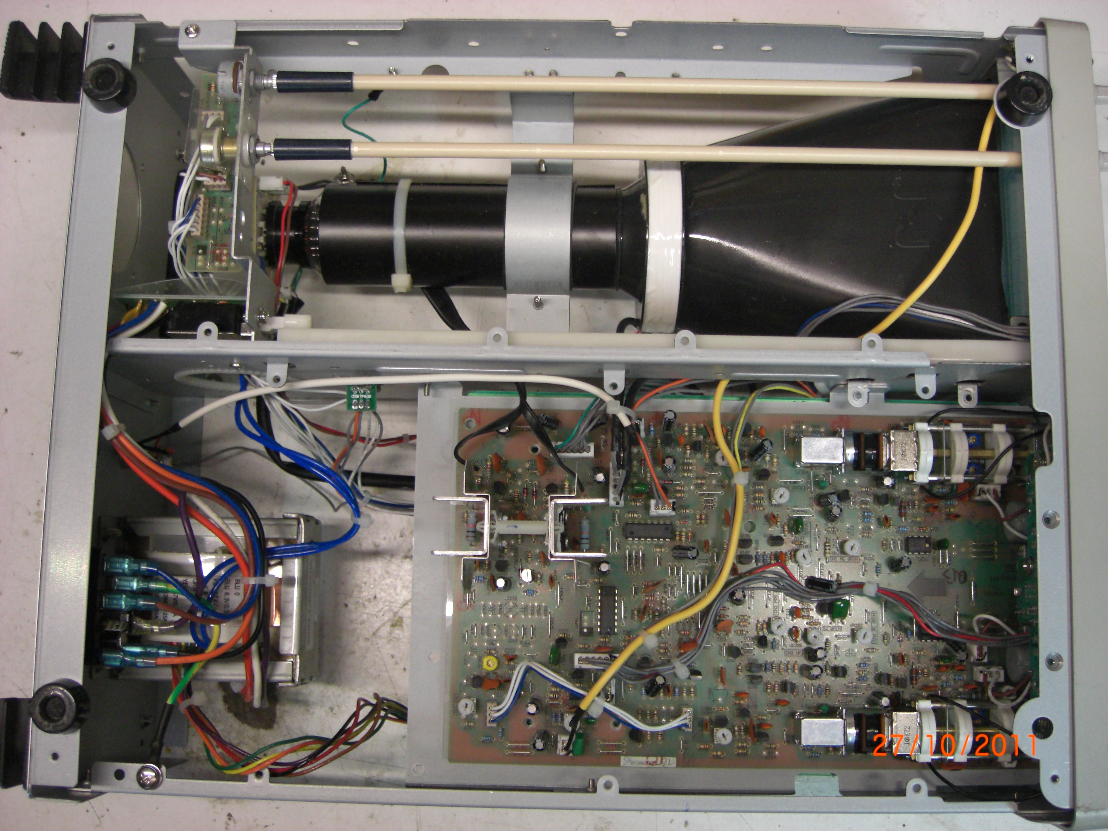
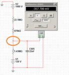
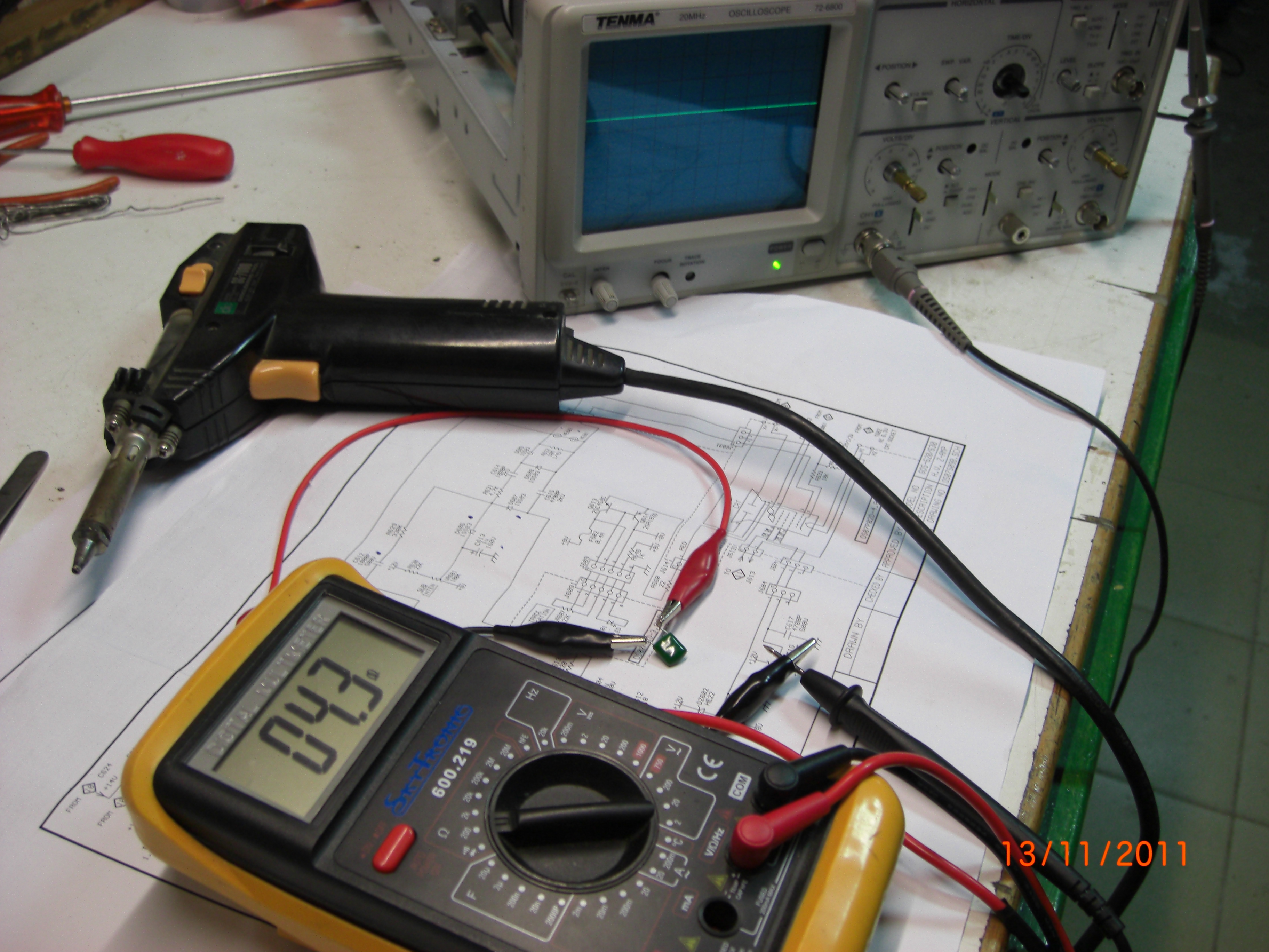
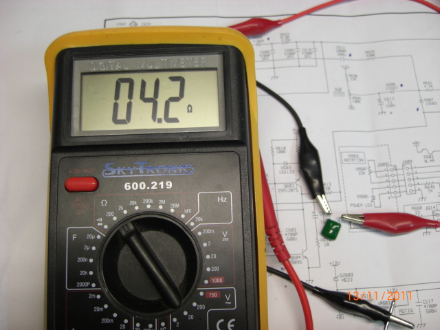
I was looking for solution on the net for my analog oscilloscope tenma 72-6800 and i find this post in edaboard.com:

"Turn up the intensity on the scope and turn down any graticule lights on the display.
Darken the room.
Switch on the scope.
After about 10sec switch of the scope while watching the display.
If you see any indication of a faint flash on the CRT then you have a very good chance that the HT (-1.9kV in your case) and heater voltages are present."

My scope does exactly that...
Please help me to find a solution.
I have electronic skill´s and a small workshop in my father house.

Thanks.
 

Have you opened up the scope? Can you see the insides of the CRT? Can you see signs of beam, or beam motion, on the inside surface of the CRT?

Do you hear any sound inside? Arcing, etc.? Just one little snap may be your high voltage finding a path to ground instead of to the electron gun.

Do you get different behavior when you first switch it on, compared to when the tubes have warmed up?

Here's a couple of recent threads about the same problem. See if they might provide you with clues as to symptoms, diagnostic methods, circuit operation, etc.

https://www.edaboard.com/threads/210797/

https://www.edaboard.com/threads/224953/
 
  • Like
Reactions: bobdob

    V

    Points: 2
    Helpful Answer Positive Rating

    bobdob

    Points: 2
    Helpful Answer Positive Rating
Hello.

Thanks for answering to my call...
I have read all that treads and i think my problem is different, theres no noise near the CRT and this is new model with little use.
I have look all two boards for suspects components and bad welds...I found nothing, everything looks good..
Please give me a clue where to start.. I send photos in attach and youtube video.

Oscilloscope-No Trace-On/Off Signal - YouTube


Can you tell more or less where is "DC restoration circuit" or "
"blanking circuit".

Thanks in advense...
 

Sorry, I don't know any specifics about your scope model.

The photos are large and detailed. Nothing seems amiss. I watched the video but couldn't spot whatever I was supposed to.

If the beam appears when the scope is switched off but not while it's on... This suggests another circuit is drawing too much power, or is drawing power directly from the hi voltage circuit. But only while the rogue circuit gets power. When no longer powered it stops draining hi V.

Just brainstorming here.

It's also possible the hi V diverts where it shouldn't while the scope is powered up. It hides. However it shows up after turning off the scope because it's at an intermediate voltage which is more prone to stay in its own wiring.

Do you see signs of scorching or overheating anywhere? Did you put your finger on components to see if they were hot?

Can you locate the hi V wire? Could it be what looks like 300 ohm twin lead, going to the circuit board near the center of the photos? Follow it. Look for carbon deposits anywhere along its length, where hi V might be drained silently when the voltage is sufficiently high.

You need to get V readings. It may be below 1900 volts while the scope is on. If it goes up to 1900 V when powering off, then you're onto something. Getting shocked is part of the job. Can't say I've ever felt 1900 volts though.

Look closely at surrounding components, whether wires are making contact where they ought not.

Do you have a service manual? Can you use a voltmeter to check the test points? Do you see printing on the chassis or circuitboards that looks like it might be voltage specs? Straight tinned posts sticking up from the board with a voltage printed next to them?

Gently pull off and push on the plug at the back of the CRT. If there's a tarnished contact then that might restore a good connection. On second thought, your OP states you get a beam flash when switching off. So leave the plug alone because it touches fragile glass.

While troubleshooting you might try using hi V from another source. (Maybe not easy to do. Just a possibility.) If you could get a beam some way, then you might spot another function of the scope is misbehaving. That section might be the one which now prevents your hi V from working.
 

    V

    Points: 2
    Helpful Answer Positive Rating

    whitspirit

    Points: 2
    Helpful Answer Positive Rating

    bobdob

    Points: 2
    Helpful Answer Positive Rating
1.

There's what looks like a neon bulb near the center of the photo. It's normal for these to go bad gradually after several years of normal operation.

It may be there as a diac, turning on when voltage across it builds to 60V (as in an oscillator circuit, or sweep deflection circuit?).

Or it may be there to indicate status as to whether something is working. Or it may be to clamp a voltage so it doesn't exceed 60V.

Tubes can become gassy. Then it may become a drain of voltage from somewhere.

Do you see the bulb light at any time when the scope is on? When you switch it off?

Try shining a light on it while the scope is on. Light is known to make a borderline neon bulb work.

It looks like an NE-2 or NE-2H. Inexpensive. Replacing it might be worth a try.

2.

If the deflection circuits are stuck at a certain voltage then your beam may be deflected way to the side.

A magnet may be able to change its direction. What if you were to hold a magnet near the CRT and move it around in an attempt to spot evidence of a beam inside?

I don't know for sure that it wouldn't hurt anything (magnetize something around the CRT). Keep a grip on the magnet so it doesn't smack the glass or anything touching it.

3.

There are potentiometers at the back of the CRT. You control them at the front. Is one for beam intensity? I can't predict whether the manufacturer would place the pot to control Hi V directly at the CRT, or put the pot in an earlier circuit when it's still at low voltage.

Anyway check for carbon deposits or anything peculiar around that area. If the pot has hi V running through it then it may need cleaning inside. This won't be easy since you need to get at the tabs on the metal cover, then pry them back, to remove the metal cover.
 
Last edited:

    V

    Points: 2
    Helpful Answer Positive Rating

    whitspirit

    Points: 2
    Helpful Answer Positive Rating

    bobdob

    Points: 2
    Helpful Answer Positive Rating
Hello.

I will try all tips this weekend, i will let you know how it went...
Many..Many.. thanks...
 

These diagrams should be very similar to your scope. See if it corresponds.

On page 11 you will find the blanking circuit as well as the dc restorer.
You should however first check all the supply voltages on pg 12 to be correct.

I include the general theory of operation of a dc restorer as well.
 

Attachments

  • GOS-620_620FG.pdf
    1.1 MB · Views: 220
  • HV_section.gif
    HV_section.gif
    74.1 KB · Views: 569
  • DC_res.gif
    DC_res.gif
    66.5 KB · Views: 345
Last edited:
Hello.

GOOD WORK.
You managed to get similar diagrams, I´:smile:am very grateful to you E-design.
I will confirm all the voltages and check the blanking circuit , dc restorer
and comment soon how it went.

ThanksThanksthanks.
 

You may encounter yet another problem. Often when trying to repair an oscilloscope you find you need another oscilloscope to check and verify waveforms.:wink:
 
Hello.

All tensions in power supply are correct , But in diagram of H.V Z-AMP found strange values like:

-In R630(22K) a read 121,9v but supposed to be 12v.But in Dc restorer general theory shows 100v same place.confused??
-In spot R610(100k)+R611(10k) it shows 121.9v supposed to be 75v.
-In cathode of Zener DZ602(H22) it shows 121.9v but should be 12v. I took off the board and test the Zener , is ok.
-In VR603(200k) i read 121.9v but supposed to 12v.
-I took off the board and test the H.V diode D604(Y10GA) but show no reading like normal diode,I think it should be so...

Can you tell what´s wrong or right. I have tested many componets all round and seem to be all ok...

Thanks..
 

You expect 12V at several points but they read ten times that. Most likely some component has fried (or partially fried), creating a short circuit (or partial short circuit) to the hi V source.

The reason you don't see 1900 volts is because it comes from a hi V source which is initially high impedance, so it drops when encountering low impedance in those low voltage circuits.

Zener 602 was exposed to 121.9 V, yet it didn't fry. This suggests either a tiny current at high V reaching, or else an open on the other side of the zener preventing current flow.

Can you test a few other components in that part of the circuit board?

Any hi V capacitors perhaps?

Can you find any point that reads 1900 V?

Suppose a component (example, hi V diode) has a deteriorating breakdown threshold. It may test properly at a low voltage with your meter. Yet it might let through hi voltage in operation and drop it to a lower value. It's hard to tell which is a bad component.

Looks as though diagnosis won't be easy. But you may be close, and diagnosis is half the battle.

Right now it's a case of 'so near yet so far'.
 
I think there is some labeling errors on the diagram.
The +12V on the SUB-INTEN most probably go to the +120V. Check with your ohmmeter if it is connected to the top side of R618 in the HV osc section (top left of diagram)

The 75V could also be labeled wrong and connected to the +120V. Check with ohmmeter.

Something may be blanking the beam by keeping point J603-3 much more negative than the -1.9kV that should be present on J603-1

One quick check I often use in such a case is to quickly short out pin 2 & 3 on the crt (with good insulated screwdriver or long nose pliers) while watching the display. You should set the scope to auto trig and say 1ms/div sweep. If you get a normal looking horizontal trace (it will be at max brightness), then you know you have a fault around some component in the dc restorer or the blanking circuit.

You should check for leaky caps and diodes in the dc restorer first. Also check the ac drive cap C612 for leakage.
C613 often go leaky as well causing other blanking problems.
If the anode of D607 is kept low for some reason (like Q604 shorted c-e), it will blank the beam effectively.

The high voltage diode will not test like a normal diode because it has a forward voltage drop, like that of a couple of diodes connected in series which most meters with diode testing can't read.
 
Last edited:
Hello.

The 12v and 75v are connected to the top side of R618 on board.
How can i check if -1,9kv are prensent in J603-3 ?I have no HV probe...there same way to make that?
Are you sure that i can quickly short out pin 2 and 3 in CRT with all connectors on, and don´t burn anything or make lot´s of sparks...Sorry to ask but i have to be absolutly sure to make such a move...
I´m will change some critical components and see what happen...
Thank´s for all guy´s..I will give news soon....
 

A rough method of checking hi V is to clip your meter lead to a resistor with value between 1M and 10M. Start with the high amount if you're not sure your meter is designed to take 1.9 kV.

Set your meter on its highest DC range.

Touch the resistor end to the HI V.

Your meter should give some kind of reading.

If so then you can figure it out based on the proportion of the attached resistor versus your meter's internal resistance on that range.

However it may not be a dead accurate figure, since hi V is generally hi impedance. So it's kind of a ballpark hi V reading.
 
I suspect the -1.9kV or something in that range to be present cause you saw the flash when turning off the power. You don't really need to measure it directly. Normal operation will keep the feedback voltage over C605 near zero volts if the HV level is correct. I just mentioned it in relation to the control grid voltage to blank or display a beam. Nothing bad will happen when you short the pins at the tube base momentarily. It will just confirm if there is a blanking issue preventing a trace being displayed on the crt.
 

Attachments

  • FB.gif
    FB.gif
    15.3 KB · Views: 209
Last edited:
Hello.
I have short it out the pins 2&3 on CRT and nothing happen, no signs of Tension, when i measued the C605 finally i found something wrong, theres a short circuit!!!!, and the C605 is the bad boy...
Thanks for all,without you guys I had not got there...
Your the best:p
 

Good job. Hope that solves it.

Question: Is a leaky/shorted cap able to explain how you got a beam flash when you shut off the unit? (Per initial post)

You'll be lucky if there isn't another bad component somewhere that failed because of the bad cap, or caused it to go bad.
 
My take is that at switch-off the condition was ideal, to briefly enable the HV osc to start up producing the beam flash on the CRT. Maybe he can make a measurement across this cap with the scope working to ensure that voltage levels is normal.
 
Hello
I have a similar problem with a TENMA 72-6800 Oscilloscope, I tell simmilar because when I turn on it the trace ilumination is normal but when I decrase the Time/Div control the trace lose ilumination and I try to adjust with INTEN control but is the higest level of intensity. If you have any idea of this issue please shared yours ideas.
 

Status
Not open for further replies.

Part and Inventory Search

Welcome to EDABoard.com

Sponsor

Back
Top