Continue to Site

Welcome to EDAboard.com

Welcome to our site! EDAboard.com is an international Electronics Discussion Forum focused on EDA software, circuits, schematics, books, theory, papers, asic, pld, 8051, DSP, Network, RF, Analog Design, PCB, Service Manuals... and a whole lot more! To participate you need to register. Registration is free. Click here to register now.

non overlapping clock generation query

Status
Not open for further replies.

juneja

Junior Member level 2
Joined
Oct 9, 2011
Messages
23
Helped
1
Reputation
2
Reaction score
0
Trophy points
1,281
Activity points
1,430

Dear Friend!
Hi
Why you don't use a simple dead time circuit to avoid overlap problem?(with a capacitor and diode and resistor and schmitt trigger not gate)
Best wishes
Goldsmith
 

I think the second one can work too.
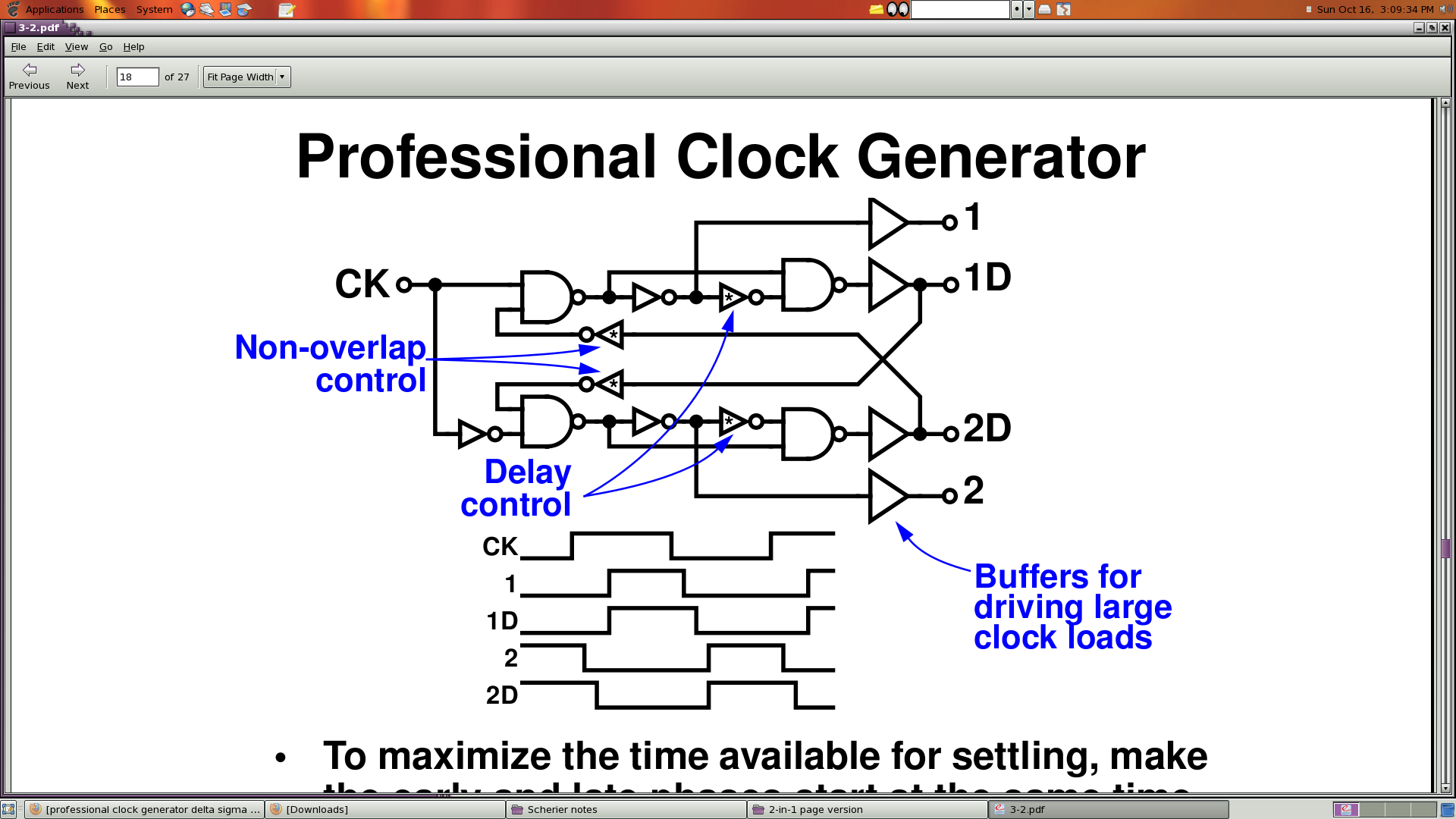
I am trying to make a two-phase non overlapping clock generator for my SC integrator. can u plz tell me why people use such a professional clock generator as this one:


(image also at : https://obrazki.elektroda.pl/46_1318777833.png)

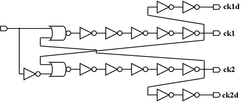
when even this one can work:


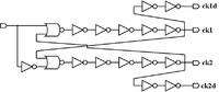
(image also at url: https://obrazki.elektroda.pl/48_1318777922.jpg)

??? i am unable to find the answer myself and fear that the second one may give up in silicon.

thanks.
 

Dear Friend!
Hi
Why you don't use a simple dead time circuit to avoid overlap problem?(with a capacitor and diode and resistor and schmitt trigger not gate)
Best wishes
Goldsmith

Thanks for your concern goldsmith.

i am avoiding RC netwroks due to chip area concerns. i want it less. also noise concerns.
thanks. can u tell me about my original query?

---------- Post added at 16:27 ---------- Previous post was at 16:26 ----------

I think the second one can work too.

exactly thats what I think... and have tested. But I want to know what are the advantages with the first one that everyone prefers the above?

thanks!

---------- Post added at 16:28 ---------- Previous post was at 16:27 ----------

and further fear that thinga may give up in silicon.
 

They are different but they both work. It is incorrect to state that "everyone uses the first circuit".
In the first example, the rising edge of the delayed clock is coming at the same time as the input falling edge. In the second example, the delayed clock is just a delayed version of the input.
 
They are different but they both work. It is incorrect to state that "everyone uses the first circuit".
In the first example, the rising edge of the delayed clock is coming at the same time as the input falling edge. In the second example, the delayed clock is just a delayed version of the input.
Now that's a precise reply! Thanks a lot JoannesPaulus! Could you also kindly clarify if it would make any difference if I use the first one or the second one in a switched capacitor integrator? I will highly appreciate your suggestions.

Thanks a lot again!
 

Could you also kindly clarify if it would make any difference if I use the first one or the second one in a switched capacitor integrator?
That depends on your circuit design. The first circuit might allow to steal some time from the previous phase and allow a longer settling for the next phase. On the other hand, the topology of your circuit is key: some designs do not work well with the first circuit and some do not work well with the second one. You need to understand your circuit!
 

It depends on what you want. In case you want to program the phase between the edges I would say use something like ring oscillator with many stages and tap out what you need.
If you want really precise use pll.
You can also connect simple current starved delay line after your oscillator and tap out what you need.
In both cases you show the difference between edges is set by prop delays of the stages. I would not call it two phase. To me if you have two phases you define exactly how delayed the edges are. Here it strongly depends on process and temperature
 

Status
Not open for further replies.

Part and Inventory Search

Welcome to EDABoard.com

Sponsor

Back
Top