danishsury
Newbie level 1
Hi everyone
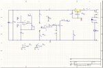
This following schematic is of a 24V DC motor speed control circuit required to handle current upto 15A.
Could anyone help me in the basic understanding of this circuit, how it works and what do the main components do.
It'll be a big help.
If you need anything else please let me know.
PS: In the schematic IC = lm324, R5 = 5.6K and R6 = 4.7K and THR- THR+ and THR S make up a potentiometer of 10K, Mosfet = IRF3205R5.
R4 = 5K and not 3.5K