Continue to Site
Follow along with the video below to see how to install our site as a web app on your home screen.
Note: This feature may not be available in some browsers.

Is it possible that i can receive it in few minutes?
") .
.Hi tpetar,
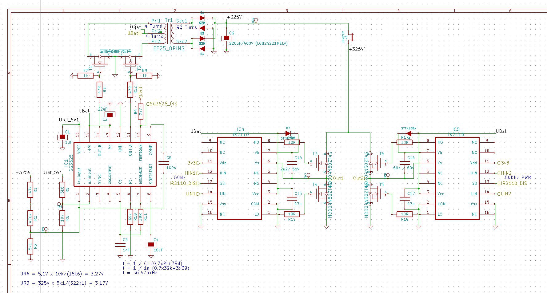
I am currently designing a inverter from 12-15Vdc to 230Vac aprox. 25va and later on 80va.
I want to us a dc-dc boost converter to boost the input dc to 325Vdc. Then I want to use a microcontroller to make a PWM to make a sine @ 230vac 50Hz.
Im going to boost the 12-15 via a hf-transformer to 325V. I have contacts that can build them for me if I gave him the windings, amps, etc. Im thinking about aprox. 40kHz for the switching frequency.
This voltage is then fed to H-Bridge which is driven by a microcontroller to create a 50Hz sinewave. Can the load be attached between the bridge? For example a lightbulb? Ofcourse some filtering is neccesary to get the hf components out.
Am I thinking in the right direction? Can you give me a hand with this?
Maybe you have some schematics laying around
My goal is to make it as small as possible.
gr,
Rohrich
.Look at UPS circuits what I send to You.
If You need individual inteligent chargers say.
Send me Your email I will send You some complete circuit solutions.
---------- Post added at 17:53 ---------- Previous post was at 17:16 ----------
Email with attachments is on the way.