Continue to Site

Welcome to EDAboard.com

Welcome to our site! EDAboard.com is an international Electronics Discussion Forum focused on EDA software, circuits, schematics, books, theory, papers, asic, pld, 8051, DSP, Network, RF, Analog Design, PCB, Service Manuals... and a whole lot more! To participate you need to register. Registration is free. Click here to register now.

Will this sensing circuit work?

Status
Not open for further replies.

hayowazzup

Advanced Member level 4
Joined
Oct 9, 2010
Messages
117
Helped
0
Reputation
0
Reaction score
0
Trophy points
1,296
Activity points
2,136
Hi all,

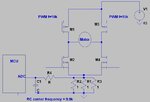
I wanted to measure the current through the motor. I am trying to use this circuit to do the work.
motor2.JPG
The output measured at the RC filter consists of spike which I think it might affect the accuracy of the sample. I have already set the corner frequency close to the switching frequency. Does anyone know how the result can be improved?
 

is it possible to eliminate the spikes and improve the accuracy of the result by just changing the resistor/capactior values?
 

is it possible to eliminate the spikes and improve the accuracy of the result by just changing the resistor/capactior values?
Increasing the capacitor will lower your corner frequency and thus reduce spikes. What speed are you sampling at?

Also - I agree with alexxx. You're either going to blow lots of power in your sense resistors or get a very small signal at your ADC. Amplification is very standard in applications like this. Also, note that with the location that you have placed your sense resistor, you cannot tell the direction of the current flow. You'll also be measuring your gate currents, which is often less than ideal.
 

Status
Not open for further replies.

Similar threads

Part and Inventory Search

Welcome to EDABoard.com

Sponsor

Back
Top