shafeey
Newbie level 3
- Joined
- Jul 29, 2009
- Messages
- 3
- Helped
- 0
- Reputation
- 0
- Reaction score
- 0
- Trophy points
- 1,281
- Location
- Bangladesh
- Activity points
- 1,308
HI, I am new to Digital Logic, and totally uninitiated with its practical side. I am trying out a little game project, actually this will be my first.
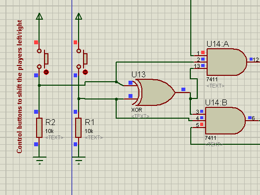
I have a row of LED, and only one player in that row( represented by a glowing LED), who will move sideways. The player always start at the middle of the row, and cannot get out of the row... So i used a 8-bit shift register which will load a predefined data value when the game is started or a reset button is pushed. For that I have to send HIGH to both S0 and S1 pin of the register only once in the beginning. Then both S0 and S1 pin will be in LOW state. An user controls the player with two buttons, which sends HIGH to either of the pins, but never to both at the same time. I have worked out the logic. But got stuck in the actual implementation with the buttons part.
When the Button is in disconnected state the pins don't get LOW, rather it's undetermined value in my proteus simulation. So the gates all act abruptly. So my question is, does this gets fixed when i put it in a breadboard? I mean in theory not having a high voltage is low, isn't it? Or do I have to use other componenets to get around the problem. I don't know much about the hardwares or the difficulties faced. So can anyone give me a brief idea of what happens in practical circuit, or any workaround?
I have included an image of my simulation...
")