Continue to Site

Welcome to EDAboard.com

Welcome to our site! EDAboard.com is an international Electronics Discussion Forum focused on EDA software, circuits, schematics, books, theory, papers, asic, pld, 8051, DSP, Network, RF, Analog Design, PCB, Service Manuals... and a whole lot more! To participate you need to register. Registration is free. Click here to register now.

Help me fix my battery charger for Li-Ion batteries

Status
Not open for further replies.

devil6600

Full Member level 5
Joined
Nov 15, 2008
Messages
250
Helped
7
Reputation
14
Reaction score
7
Trophy points
1,298
Activity points
2,931
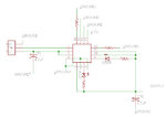
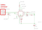
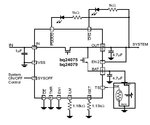
i am using bq24075 ic for li-ion battery charging but for some reason its not working. ic is functioning properly because when i connect battery to ic it detects battery(charge led blinks for a second and switches off) but it does not charge the battery. i studied the EVM schematic(**broken link removed**, page 15) of the ic but i am unable to understand. can anyone tell me what i am doing wrong in my attached schematic.

thanks
 

Attachments

  • charger.jpg
    charger.jpg
    79.2 KB · Views: 163

Re: battery charger help

hi
see attachment
battery is connected left side
 

Attachments

  • charger2.jpg
    charger2.jpg
    91 KB · Views: 162
Re: battery charger help

One of guess: TS is not connected correctly and it leads to wrong temperature detection.
 
Re: battery charger help

TS pin is soldered perfectly, i have already triple checked it.
my circuit is as per the schematic in datasheet. i have also tried grounding the TS pin with 10k resistance, it didn't worked also.
more over every pin is perfectly soldered, triple checked
please see this schematic from datasheet and mine:
 

Attachments

  • shcematic.jpg
    shcematic.jpg
    70.1 KB · Views: 136
  • charger.jpg
    charger.jpg
    79.2 KB · Views: 144
Re: battery charger help

Try grounding the TS pin with 100k or more resistance.
 

Re: battery charger help

Isn't batery already charged?
 

Re: battery charger help

battery partially charged Vbat = 3.82Volts
also tried with another battery having 4V.. didn't worked :(
 

As I know TS is usually connected to VDD thru a resistor. In the battery, Ts is connected to ground thru another resistors.
So TS voltage is the divided VDD voltage by two resistors for temperature detection.
 

Did you studied datasheet,
https://www.ti.com/lit/ds/symlink/bq24075.pdf
Do you get Power-Up, Power-Down, Po Power-Up, Power-Down, Power Good Indication . Is input voltage is in proper range(4.3V to 6.4V max) showing power Good Indication? See un page 26. Temperature range is from 0-50c. You have to set thermister value accordingly, see on page 28.
TS Function
Use a 10kΩ NTC thermistor in the battery pack (103AT-2). For applications that do not require the TS monitoring function, connect a 10kΩ resistor from TS to VSS to set the TS voltage at a valid level and maintain charging.
Sorry 100K won't work.
 
Last edited:

thanks for advice, can you please tell me how much voltage should be maintained on TS pin for proper functioning?
 

You don't have to worry about voltage on TS pin. Put 10K resistance as datasheet describes.
For applications that do not require the TS monitoring function, connect a 10kΩ resistor from TS to VSS to set the TS voltage at a valid level and maintain charging.
And also maintain input voltage around 5V, for example from USB port of your computer.
 

thank you members for all your advice. someone on another forum suggested me to use bq24074
so i am changing the chip to bq24074
 

If your input is greater than 6.5V only then bq24074 will make a difference. It will work upto 10.5V. For better learning experience its better you fix the circuit you already assembed.
 

Status
Not open for further replies.

Similar threads

Part and Inventory Search

Welcome to EDABoard.com

Sponsor

Back
Top