Welcome to our site! EDAboard.com is an international Electronics Discussion Forum focused on EDA software, circuits, schematics, books, theory, papers, asic, pld, 8051, DSP, Network, RF, Analog Design, PCB, Service Manuals... and a whole lot more! To participate you need to register. Registration is free. Click here to register now.
Is it possible to see sub harmonic oscillation in simulation environment, when a buck converter is run at duty cycle ~60% and feedback is load current?
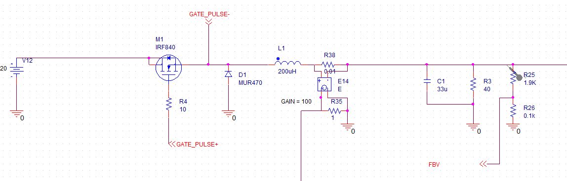
can you advice why I do not see the same in following circuit? circuit and waveform are given below.
Circuit is simple stepdown regulator, running in continuous conduction mode. controller is PI, feedback is inductor current. Inductor current is directly fed at input of error amplifier, reference is DC voltage, so I believe this would be average current mode control.
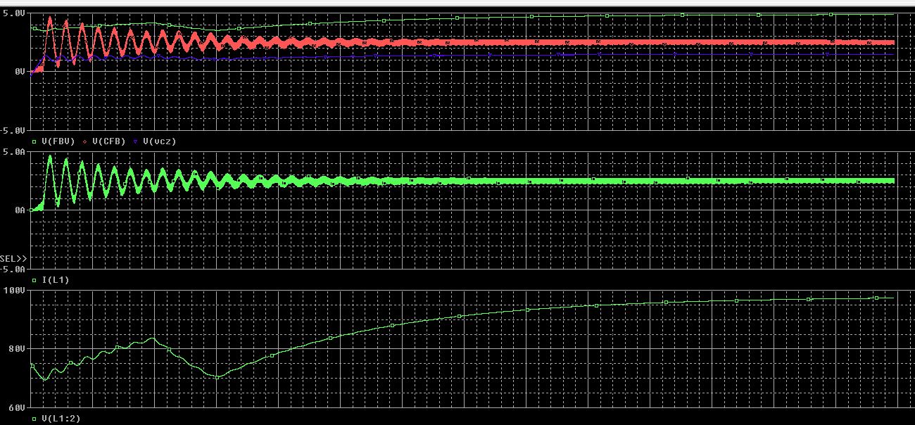
In attached waveforms circuit is opearting close to 75% duty cycle. At the there are few oscillation and but these are settled after a while.
In waveform picture: Top plot consist of current feedbacksignal (V(CFB), Controller output (V(vcz))
Bottom most plot is outout voltage.
Can you please advice why I do not see subharmonic oscillation in this circuit?
I am getting similar kind of response when I choose switch current as feedback?
I don't understand how the waveform with V near 100 V is related to a buck converter circuit with 20V input supply.
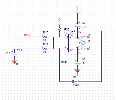
Subharmonic oscillation, if occuring, is a matter of the switch mode controller, so you should primarly show the controller circuit for a discussion of the effect.
As far as I'm aware of, the oscillation occurs in a controller working on peak current, e.g. in an industry standard UC3842 without slope compensation.
If you're using an actual compensated error amplifier for the current control loop, then yeah it's average CMC, which normally does not see subharmonic oscillation (it can if its loop gain is too high at the switching frequency).
Sorry, seems that image is cropped, here input voltage source is 120v not 20. I have build my own control circuit and would try to explain below.
inductor current is feedback to an opamp circuit which, doubles up as error amplifier and PI controller (here cfb is inductor current)
output voltage of this stage is compared with a sawtooth waveform and gate pulse corresponding to error voltage is generated. This pulse (through latch & appropriate driver) drives the gate of mosfet.
This site uses cookies to help personalise content, tailor your experience and to keep you logged in if you register.
By continuing to use this site, you are consenting to our use of cookies.