Vermes
Advanced Member level 4

Assumptions
- clock should have alarm
- it should consists of TTL circuits
- short construction time
- low costs
- modular design, that makes it easy to run, as well as subsequent working analysis
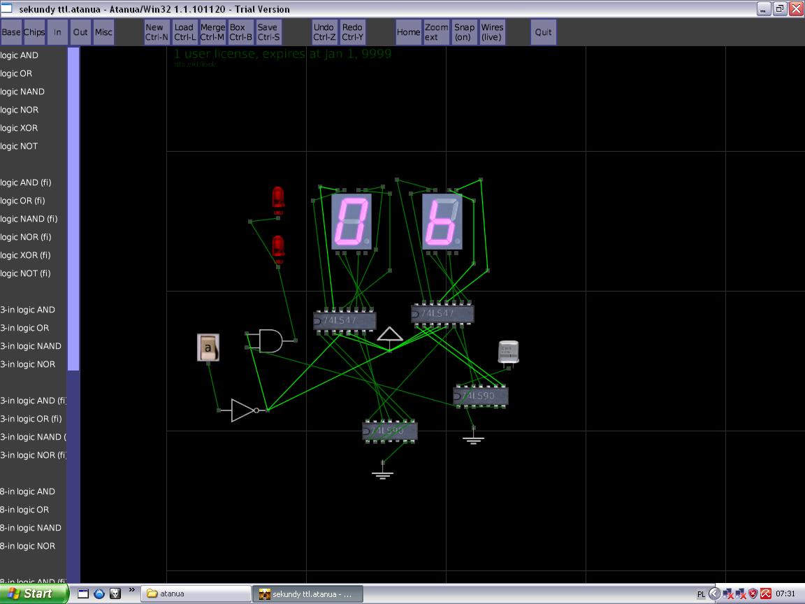
First simulations were made in Atanua program. Then plates in KiCAD were programmed.
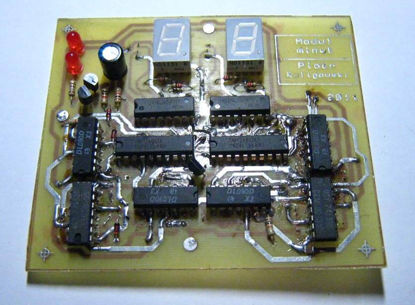
Overall construction
About 30 circuits were used for the construction. The clock was divided in modules in order to make it easier and quicker to start:
- seconds module – counters of seconds tens and unities with transcoders for 7-seg code;
- minutes module – counters of minutes tens and unities, doubled for alarm clock and clock settings, a selector choosing what should be transferred by 7-seg transcoders (alarm clock or clock). Also a comparator for EX-OR comparing whether the minutes in the alarm clock memory are equal to the clock minutes;
- hours module – counters of hours tens and unities, also doubled for alarm clock and clock counter. Also the source selector – the selector to what is to be displayed by 7-seg transcoders;
- alarm clock module – collects the signals from comparators, checks if it has permission for the alarm clock and if the comparators allow it, the sound generator is running on three unstable generators;
- power supply module – provides 5V DC 1,5A to every circuit;
- control module – it's built of microcontroller instead of TTL circuits. It's a quick and safe solution. It is responsible for sending the signal to the seconds module in the frequency of 1Hz, to the minutes module 1/60Hz and to the hours module 1/3600Hz. Additionally, it supports the control keyboard and switches the modules between the display mode of the clock and alarm clock. It also sends signals that allow or forbid to activate the alarm clock.
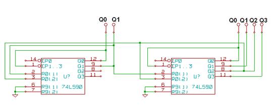
To built the seconds, minutes and hours counters, the decade counters 74ls90 were used. They are equipped with 4 JK triggers, zeroing circuit, the circuit that set 9, BCD output and two clock inputs. Properly configured, they can work as MOD6, MOD10 and MOD24 counter, all three used in the construction of this alarm clock.
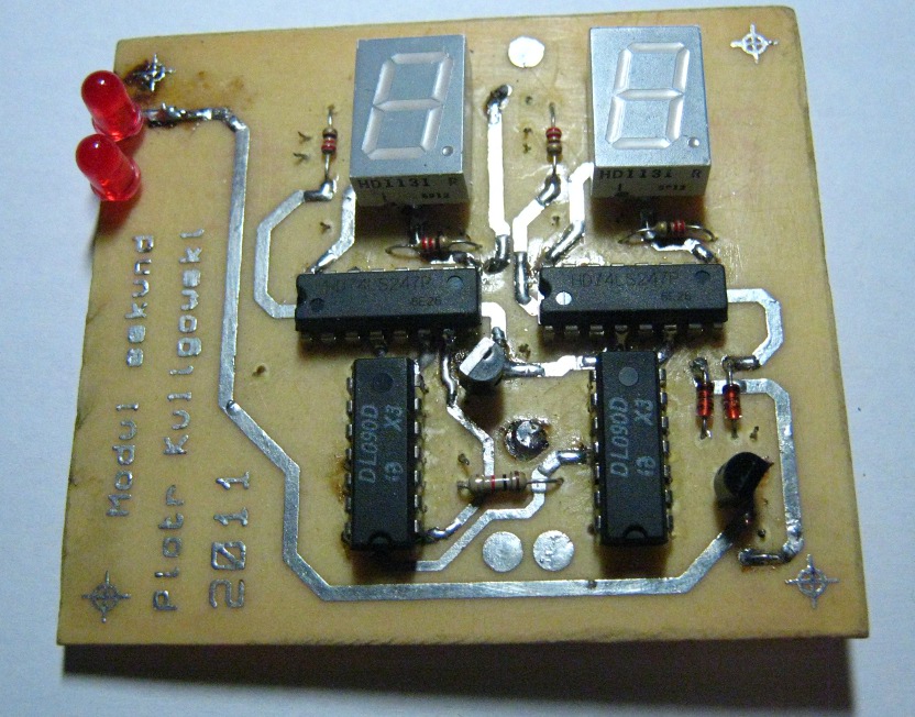
Seconds module
It consists of one set of MOD6 and MOD10 counters, because in the alarm clock display mode the seconds aren't displayed. As the easiest module, it was started as first one.
 **broken link removed**
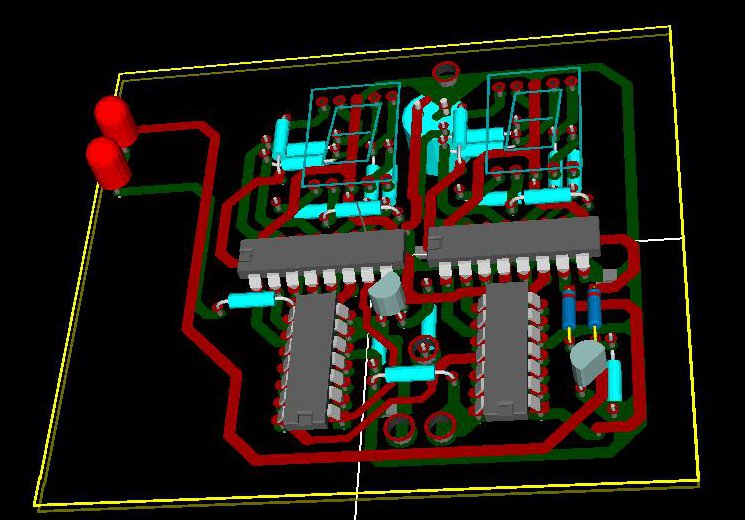
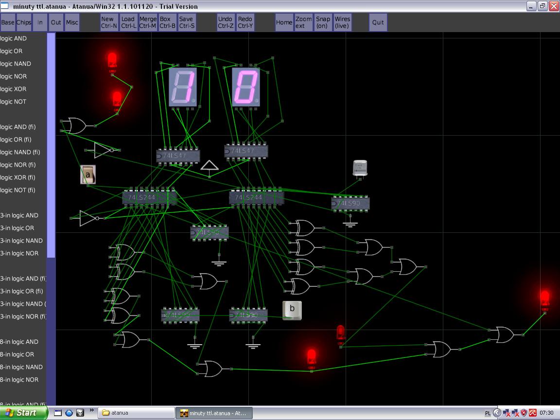
Minutes module
The minutes counter 0-59 consists of MOD10 and MOD6 counters connected in series. A separate set of counters is for the alarm clock and for the clock. The choice between displaying minutes and the alarm clock can be done by setting the proper mode on SET rail. The circuit, which switches the source of signal for the display transcoders, is three-state buffers. Here they act as the source selector. EXOR gates compare the alarm clock and clock state. They are connected by outputs via multi-input OR gates. A local resetting circuit sets zeros on each counter directly after activating.
 **broken link removed**
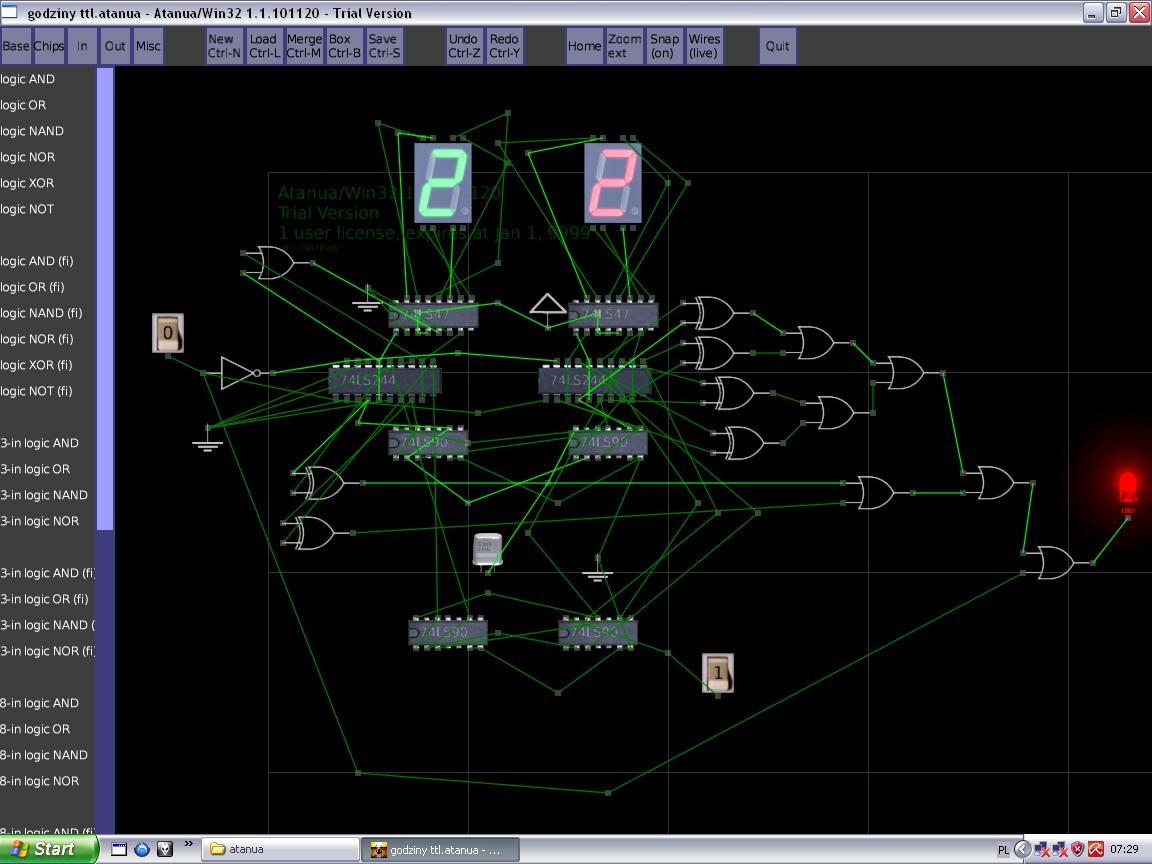
Hours module
Like the minutes module, it consists of separate set of counters for the clock and alarm clock, EX-OR comparator and the source selector. Counter circuit modulo 24 with BCD output was used here. It was self projected by using two decade counters 74LS90. Additionally, in this circuit there is a system that deletes zero before an hour. It prevents displaying '06:54.04'. Instead of this, the clock displays '6:54.04'.
 **broken link removed**
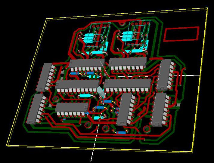

Power supply module
Transformer, rectifier, filter, stabilizer, condensers preventing raising and radiator together make the most simple power supply. After activating, it turned out, that the TTL circuit consumes a lot of current – it took up to 1A, the losses in radiator were so big, that its temperature raised to more than 100 degrees Celsius. The originally planned bridge rectifier was reworked into the wave rectifier on two diodes SR560. That made the losses fell twice. Fortunately, this alteration did not cause a large increase ripple at 1A. To be sure, an electrolytic capacitor should be increased.
Schema with the bridge:

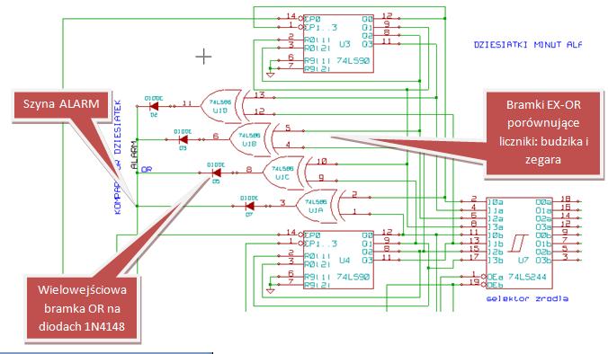
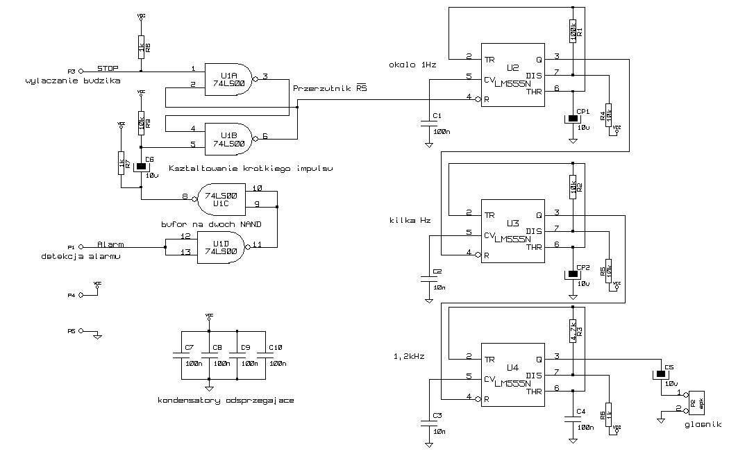
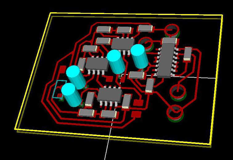
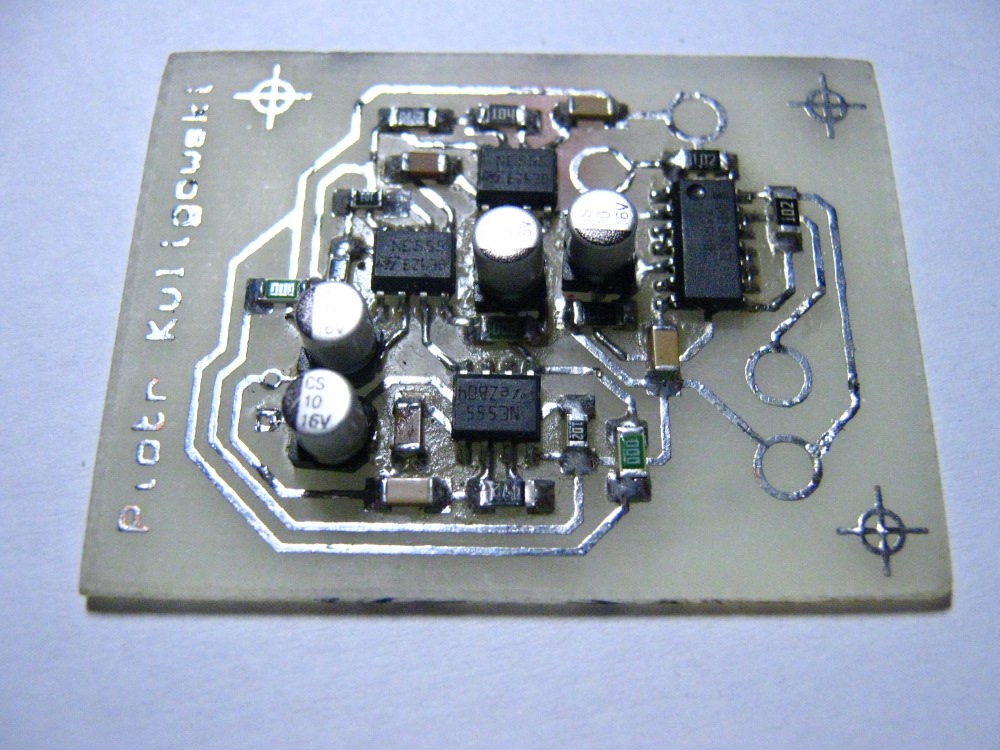
The alarm clock module
EX-OR double-input gates are responsible for comparing the counter of hours or minutes of the clock and the alarm minutes. One of the inputs is connected to the minutes (or hours) counter of the clock, the second one is connected to the minutes (or hours) counter of the alarm clock. Signals from EX-OR gates are collected to one rail via multi-input OR gates realized on 1N4148 diodes (additionally, there is a pull-down resistor on the plate, it eliminates undefined states). That rail was named ALARM. In the moment of low state on the rail, the signal of the alarm clock is activated – it is generated by three unstable multi-vibrators on NE555. That is why the sound reached is similar to each alarm clock sound.
Resetting circuit
Constructing the resetting circuit prevents situation that after activating the clock, a random time like '11:89.67' is displayed. After turning on, the resetting circuit zeroes all the counters. It was done on a series RC circuit and the signal of this circuit was distributed to each counter.

Control module
A microcontroller with a simple program replaces complicated network of gates, which was intended to be used instead. The plate was drawn with a oil marker and digested. The whole program was something about 50 lines.
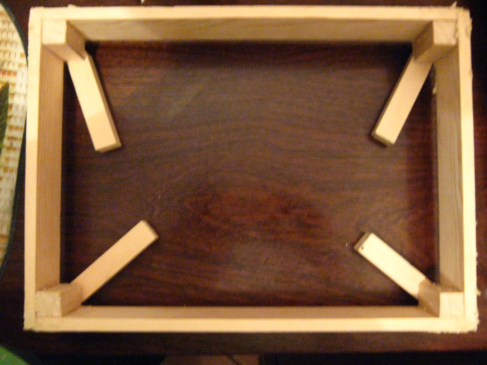
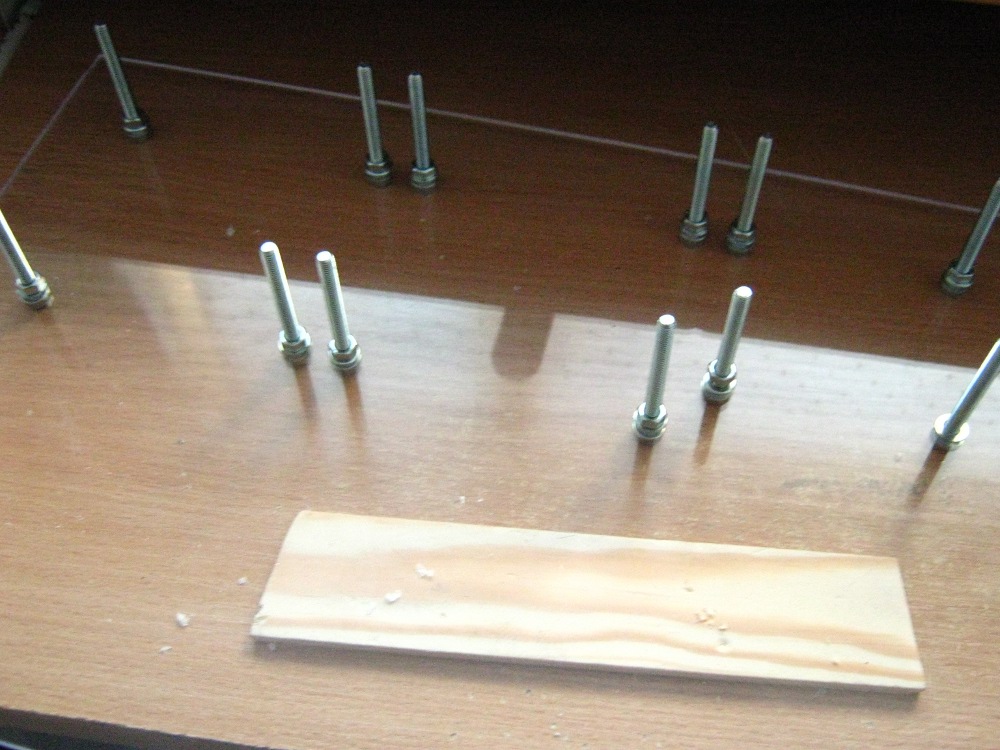
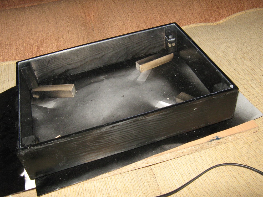
Housing
The housing was made of bars of 5cm width linked with screws and filler in the corners. Everything was dyed with black paint. Upper and lower cover are made of plexiglass 5mm.


Link to original thread (useful attachment) – Projekt zegara TTL z budzikiem