Continue to Site

Welcome to EDAboard.com

Welcome to our site! EDAboard.com is an international Electronics Discussion Forum focused on EDA software, circuits, schematics, books, theory, papers, asic, pld, 8051, DSP, Network, RF, Analog Design, PCB, Service Manuals... and a whole lot more! To participate you need to register. Registration is free. Click here to register now.

[SOLVED] How to find the values of the components

Status
Not open for further replies.

shetty_18

Newbie level 5
Joined
Aug 29, 2011
Messages
10
Helped
0
Reputation
0
Reaction score
0
Trophy points
1,281
Activity points
1,363
Current measurement circuit

Hello,

I am currently working on my thesis,i am not very good at analog circuits.This is a small part of my thesis.
I have a circuit which is current measurement circuit.This circuit was already designed and tested by some ex-thesis student.Now i have to use the same circuit to measure the current through a shunt which is connected to a motor simulator.

**broken link removed**

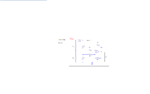
The circuit diagram is attached above..input voltage is 25 v,R sens is 0.1ohm (Rshunt) and the current i have measure is 3.5A.
1. Can you please help in finding the value for resistors.
2. I want to simulate the circuit in LT Spice..while doing so should i connect a load at the output of the op amp...?
3. Or should i connect the load to branch which is depicted as branch 1 in the circuit.where exactly in the circuit can i get the current i am measuring..?

i understand that the voltage Ua,is the voltage which is proportional to the current i have to measure.

Thank u al in advance..??
 

Attachments

  • Untitled.png
    Untitled.png
    47.1 KB · Views: 95
Last edited:

Re: Current measurement circuit

input voltage is 25 v,R sens is 0.1ohm (Rshunt) and the current i have measure is 3.5A.
1. Can you please help in finding the value for resistors.

If 25V is also the supply voltage for the opAmp, use Ra=Rb=Rc=Rd = 1..10kΩ , R1=R2=100kΩ , and R3=R4 depending on your required gain = R3/R1 = R4/R2 . Their absolute values aren't critical, but their tolerance should be 0.1 .. 1% . In this case, the quiescent output voltage Ua (@ Isens=0) will be about 25V/2 .

A current of 3.5A creates a voltage drop of 0.35V at Rsens -- which is (differentially) divided by 2 -- so with a gain of 20 (R3=R4=20*R1=2MΩ) this achieves an opAmp output deviation of 3.5V , i.e. Ua=12.5V+3.5V=16V .

2. I want to simulate the circuit in LT Spice..while doing so should i connect a load at the output of the op amp...?
Yes. A realistic one, suggest ≧ 1kΩ .

3. Or should i connect the load to branch which is depicted as branch 1 in the circuit.
No.

where exactly in the circuit can i get the current i am measuring..?
At the opAmp output.

i understand that the voltage Ua,is the voltage which is proportional to the current i have to measure.
Correct. With an offset of power-supply-voltage/2 , however. If you don't want this, you need a symmetrical power supply for the opAmp, e.g. ±12V -- but then you would have to change the ratio Ra/Rb=Rc/Rd .
 
Re: Current measurement circuits

Thank you very much for your reply...

1.the supply voltage for the op amp is symmetrical power supply of ±15V.sorry for not mentioning in the previous thread.
so now what difference does this make for the values of resistors.

2.some additional info : the input voltage is 25 v sine wave(0 to 25v)(12.5 amplitude and 12.5 dc offset)
 

Hey my friend!
Here is the formula: Value of r4 = r3 . and value of r1=r2
and its voltage gain =(vrb-vrd)*(r4/r2)
Respect
Goldsmith
 

Re: Current measurement circuit

Hello,

I am currently working on my thesis,i am not very good at analog circuits.This is a small part of my thesis.
I have a circuit which is current measurement circuit.This circuit was already designed and tested by some ex-thesis student.Now i have to use the same circuit to measure the current through a shunt which is connected to a motor simulator.

op amp supply voltage is +/- 15 volts and i also know that Ra = Rc, Rb=Rd, R1=R2, R3=R4


The circuit diagram is attached above..input voltage is 25 v,

case (1)R sens is 0.1ohm (Rshunt) and the current i have measure is 3.5A.
case (2)R sens is 3.467ohm (Rshunt) and the current i have measure is 1.5A.

1. Can you please help in finding the value for resistors.
2. I want to simulate the circuit in LT Spice..while doing so should i connect a load at the output of the op amp...?
3. Or should i connect the load to branch which is depicted as branch 1 in the circuit.where exactly in the circuit can i get the current i am measuring..?

i understand that the voltage Ua,is the voltage which is proportional to the current i have to measure.

Thank u al in advance..??
 

Attachments

  • Untitled.png
    Untitled.png
    47.1 KB · Views: 66

Re: Current measurement circuits

1.the supply voltage for the op amp is symmetrical power supply of ±15V.sorry for not mentioning in the previous thread.
so now what difference does this make for the values of resistors.

2.some additional info : the input voltage is 25 v sine wave(0 to 25v)(12.5 amplitude and 12.5 dc offset)

I think you can keep the old values, but connect the foot points of Rb & Rd to the neg. power supply (-15V) instead of GND.
This results in an input common voltage range (ICMR) between ((25V-(-15V))/2)-15V=+5V and ((0V-(-15V))/2)-15V=-7.5V , which your opAmp should manage, see its dataSheet.

For the real circuit you'd probably want to compensate the opAmp's input offset voltage in order to zero adjust the output voltage to 0V @ Isens=0 . For this, insert a zero-adjust poti of 0.1 .. 0.2% of Ra=Rb=Rc=Rd (i.e. 10..20Ω for Rx=10kΩ) between Ra & Rb , center tap to R1 (or between Rc & Rd , and center tap to R2). I'd suggest a multi-turn trimmer like this one from BOURNS or that one from VISHAY.
 

I don't see a purpose to place more resistors than necessary and would omit R1 and R2 as first step. Then R3/R4 to Ra/Rc are setting the voltage gain. Rb/Rd are forming an additional voltage divider to keep the OP input voltage within common mode range. They don't directly affect the gain setting, but cause additional errors due to resistor mismatch. Acceptable power dissipation has to be considered too when choosing Ra-Rd.
 

I don't know what is your signal's frequency, but I'd rather use integrated instrumentation amplifier such as AD620 from Analog Devices ($8.65 from Digikey) or integrated differential amplifier such as INA105 from Texas Instruments ($9.63 from Digikey).

Such devices mostly eliminate problems concerning resistor value deviations while significantly improving noise performance.
 

but I'd rather use integrated instrumentation amplifier
For the present application, standard instrumentation amplifiers aren't an option, because they don't provide a sufficient common mode range.
 

Status
Not open for further replies.

Part and Inventory Search

Welcome to EDABoard.com

Sponsor

Back
Top