enrico
Member level 3
Dear All,
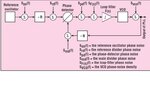
I have a non traditional PLL block with attenuator and mixers in between the closed loop. Could someone confirm the followin when modelling PLL Noise (Total Phase Noise Contribution) :
- If in case I have an attenuator (or passive double balanced mixer) in between the blocks, how its invidivual phase noise is seem as a contribution since it is a passive device ? Still, Should I consider the phase noise as f^0 (white phase) or just a thermal noise (k0) ?
- How can I model it in terms of numerical k term ? I mean thermal noise which shows zero dB/Dec slope region.
- What about the own insertion loss that in fact provides desensibilization (noise) but appers to not disturb SSB phase noise ?
Thank you in case someone can drop some ideas.