Continue to Site

Welcome to EDAboard.com

Welcome to our site! EDAboard.com is an international Electronics Discussion Forum focused on EDA software, circuits, schematics, books, theory, papers, asic, pld, 8051, DSP, Network, RF, Analog Design, PCB, Service Manuals... and a whole lot more! To participate you need to register. Registration is free. Click here to register now.

[SOLVED] up/down counter using 74LS192

Status
Not open for further replies.

DarkDome

Newbie level 5
Joined
Sep 16, 2011
Messages
10
Helped
0
Reputation
0
Reaction score
0
Trophy points
1,281
Activity points
1,340
hi guys.. i am having a problem constructing an up/down counter that counts from 00 - 99 and then automatically counts down to 99 - 00.
pls reply asap:)
 

This counter configuration is supposed to accept external pulses or not ? (This means counting up/down pulses are automatically (internally) generated by the circuit).
 

Try this way
 

Attachments

  • counter  up_down 99.JPG
    counter up_down 99.JPG
    83.4 KB · Views: 874
it has a clock pulse using 555 timer.. after the last count which is 99 the counting will automatically counts down to 00.

---------- Post added at 05:23 ---------- Previous post was at 05:08 ----------

what does U1, U2, U3 mean?
 
Last edited:

U1, U2 = inverter gate
U3= or gate

still need to reconsider this circuit, it's not working. :roll:
 
Thanks bro, i hope it will work:cool:
 

Sorry, I have tested and the circuit it’s not working. By the way, are you limited to use the 74LS192 series or you can choose from other BCD counters?
 

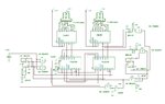
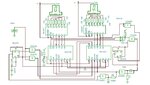
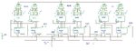
See a new diagram, not the best solution, just a small experiment... :-D

Still there’s a small glitch at changing from counting up to down and vice versa, that’s why we obtain shorter pulses counting down from 98 to 97 and counting up from 01 to 02 than the normal pulses…
That’s more visible on low frequency clock.


Attachments

  • 99 counter_up_down.JPG
    99 counter_up_down.JPG
    159.9 KB · Views: 449
Last edited:
I tried some simple circuit modifications that seem to improve counting. Now it’s working fine. See the video details. :-D


Attachments

  • 99cnt.JPG
    99cnt.JPG
    195.4 KB · Views: 649
thanks man.. :-D

I have another project which is a digital clock with hour, minutes and seconds still using 74192.. hope you can you can help me with it;-)
 
Last edited:

Yeah, that might be our last project and probably the most complicated one.. :-|
by the way which is better, using 7-segment or LCD display for this one?
 

One idea for the 24h clock:
 

Attachments

  • 24h clock.JPG
    24h clock.JPG
    269.3 KB · Views: 590
thanks,
how about for the 12hour digital clock with switch for the sec. min. and hour for it to adjust?
 
Last edited:

I would assume there’s no need for seconds adjustments, minutes and hours only… :-D
 

Attachments

  • 12 h clock adj.JPG
    12 h clock adj.JPG
    290.1 KB · Views: 278
minutes and hours adjustments are OK but much better if seconds is included..:-D

can I use any value for the resistors?
 
Last edited:

OK.
32Khz crystal oscillator using the IC CD4060 included... :cool:
 

Attachments

  • 12h clock_xtal.JPG
    12h clock_xtal.JPG
    502.6 KB · Views: 226
Pull-up resistors = 10K-22k
Pull-down resistors (R44, R43, R46)= 1k
All series LED resistors 100-150 ohms
R45=10M
C1, C2 = 12-22pF
 
thanks man :-D this would be a great help:-D

by the way we are given a condition that we have to PAUSE the time before we can adjust the hour,minutes and seconds.
 
Last edited:

can I use 555 timer instead of CD4060? and just add a JK or SR flipflop as a debounce circuit?
 
Last edited:

Status
Not open for further replies.

Part and Inventory Search

Welcome to EDABoard.com

Sponsor

Back
Top