Continue to Site

Welcome to EDAboard.com

Welcome to our site! EDAboard.com is an international Electronics Discussion Forum focused on EDA software, circuits, schematics, books, theory, papers, asic, pld, 8051, DSP, Network, RF, Analog Design, PCB, Service Manuals... and a whole lot more! To participate you need to register. Registration is free. Click here to register now.

Simulation problem with pspice model of memristor

Status
Not open for further replies.

Memristor

Newbie level 6
Joined
Sep 14, 2011
Messages
12
Helped
0
Reputation
0
Reaction score
0
Trophy points
1,281
Activity points
1,375
Hi,
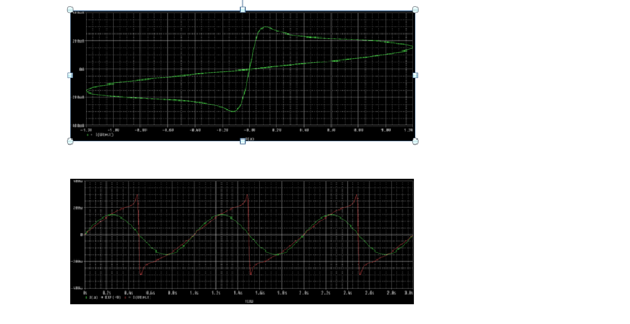
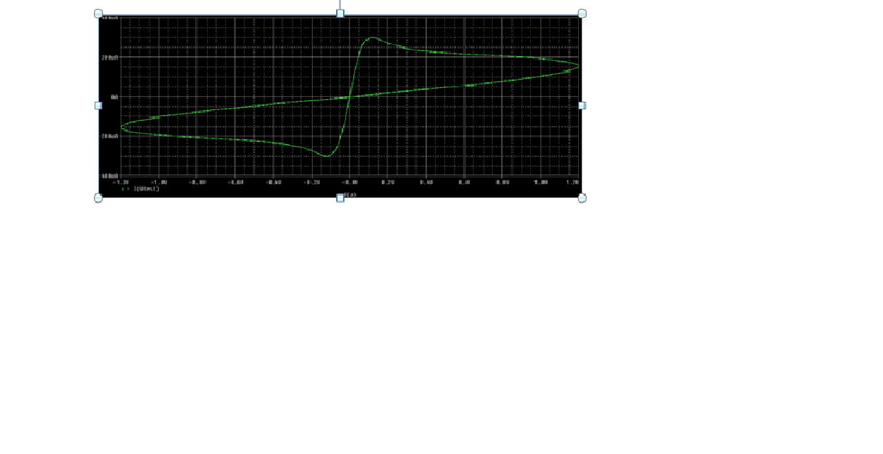
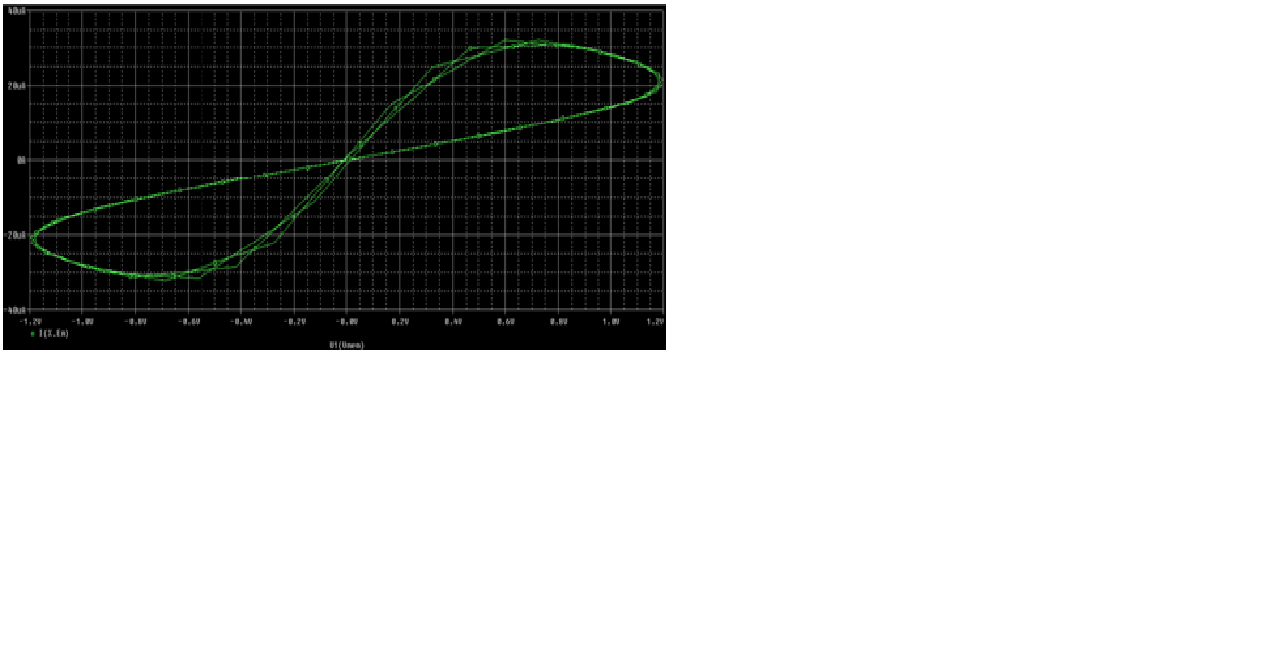
i'm trying to do a simulation pspice of memristor,but when i run simulaion i don't obtain the pinched hysteresis loop of memristor.Can you help me? This is the pspice netlist .... are there mistakes?

* Ron, Roff - Resistance in ON / OFF States
* Rinit - Resistance at T=0
* D - Width of the thin film
* uv - Migration coefficient
* p - Parameter of the WINDOW-function
* for modeling nonlinear boundary conditions
* x - W/D Ratio, W is the actual width
* of the doped area (from 0 to D)
*
.SUBCKT memristor Plus Minus PARAMS:
+ Ron=100 Roff=16K Rinit=11K D=10N uv=10F p=10

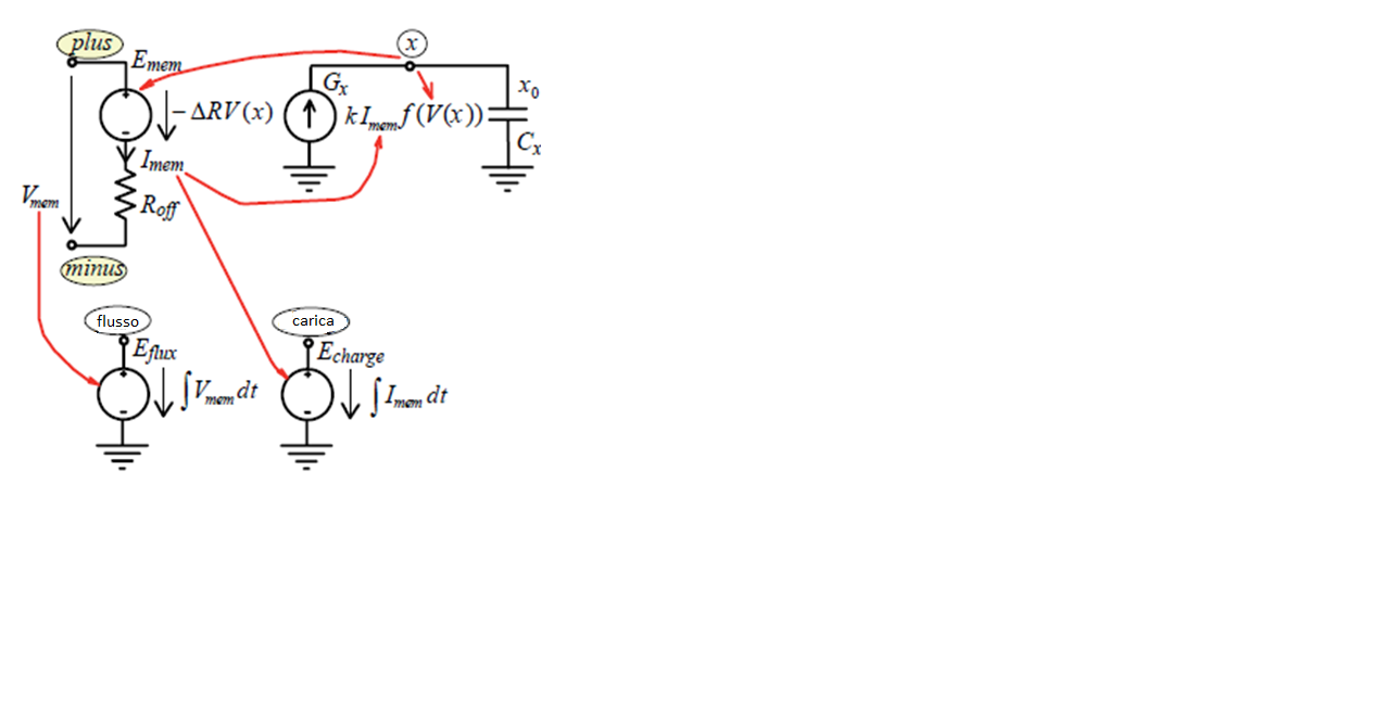
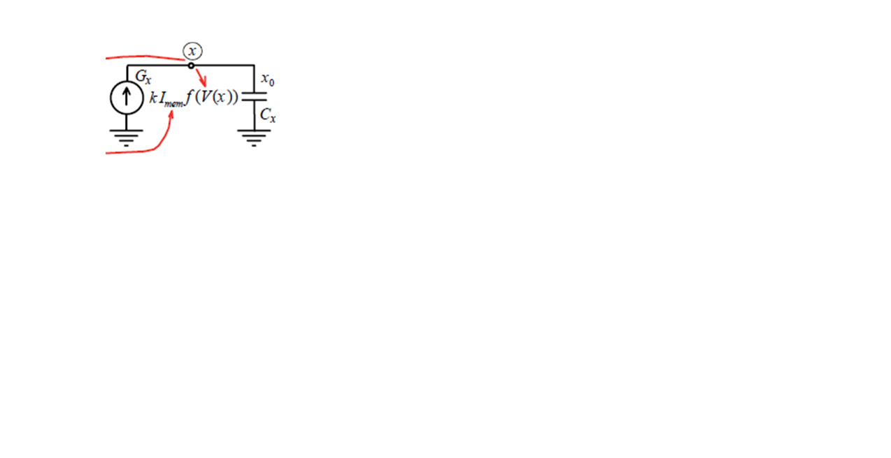
* DIFFERENTIAL EQUATION MODELING *

Gx 0 x value={ I(Emem)*uv*Ron/D^2*f(V(x),p)}
Cx x 0 1 IC={(Roff-Rinit)/(Roff-Ron)}
Raux x 0 1T
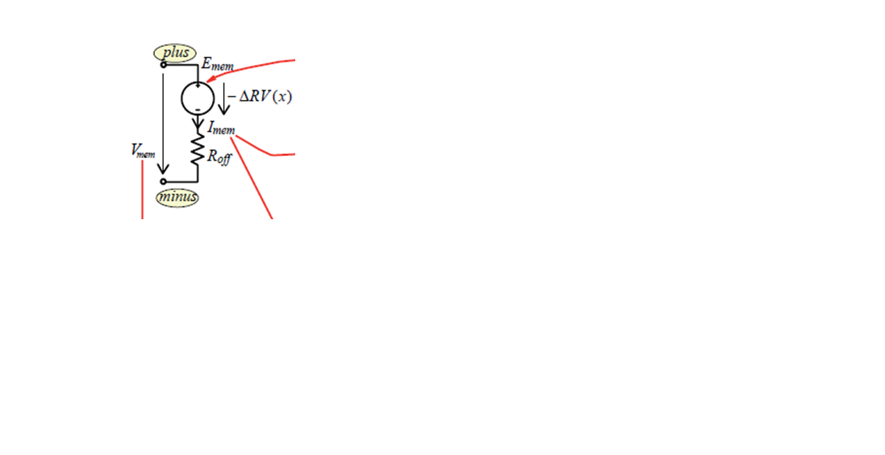
* RESISTIVE PORT OF THE MEMRISTOR *

Emem plus aux value={-I(Emem)*V(x)*(Roff-Ron)}
Roff aux minus {Roff}

*Flux computation*

Eflux flux 0 value={SDT(V(plus,minus))}

*Charge computation*

Echarge charge 0 value={SDT(I(Emem))}

* WINDOW FUNCTIONS
* FOR NONLINEAR DRIFT MODELING *

*window function, according to Joglekar
.func f(x,p)={1-(2*x-1)^(2*p)}
*proposed window function
;.func f(x,i,p)={1-(x-stp(-i))^(2*p)}
.ENDS memristor

Xmemrist aa 0 memristor
Vtest aa 0 SIN(0 1.2V 1 0 0 0)

.tran 0 3s 0 3m skipbp
.probe
.end

After "Run Test" i do:
Trace---->Add New Trace---->V(aa)-I(Vtest).....is correct?

Thanks,
Memristor
 

Re: Problem pspice model of memristor

Is this the result you get?


Keith.
 

Re: Problem pspice model of memristor

i don't understand how you obtain the first graphic. The second one is ok:)..but you have not got the pinched hysteresis loop of memristor.
another question: can you explain how ""Raux x 0 1T"" means?

Thanks,
Memristor
 

Re: Problem pspice model of memristor

The first plot is simply what I assumed you were interested in - resistance = V(aa)/I(Vtest). It does actually show hysteresis, but it is not obvious. At t=0 the voltage is zero and the resistance is around 11k. At t=0.5s the voltage is also zero but the resistance is less than 1k. If you plot resistance against V(aa) rather than time then you get this:


which shows the hysteresis better.

Raux x 0 1T is simply a 1 Tera ohm resistor between nodes x and 0.

Keith.
 
Re: Problem pspice model of memristor

I managed to get these two graphics:


what do you think?
The first plot should be the pinched hysteresis loop of memristor.

another question :) : can you explain how ""Xmemrist aa 0 memristor"" means?

thanks,
memristor
 

Re: Problem pspice model of memristor

I cannot read what the axes are on your graphs.

The memristor is defined as a subcircuit - from the .SUBCKT to the .ENDS. The X... is the subcircuit call which actually uses it.

As far as I can see the model works. Whether it is accurate is another matter - I have not dealt with memristors before.

Keith
 
Re: Problem pspice model of memristor

ok thanks for your help.

Memristor
 

Re: Problem pspice model of memristor

i don't understand how you obtain the first graphic. The second one is ok:)..but you have not got the pinched hysteresis loop of memristor.
another question: can you explain how ""Raux x 0 1T"" means?

Thanks,
Memristor

If you want to see pinched hysteretic loop, you should arrange the x-y plot as shown by Keith, but with the voltage across memristor at horizontal axis and the current at vertical axis. Note that according to SPICE conventions, the current flowing through the excited voltage source is minus the current flowing through the memristor (which should appear at vertical axis).
Hope this helps you.
Dalibor
 

Re: Problem pspice model of memristor

Hi Dailor,
I have not figured out what must be the result. i have modified the spice code in this way:

.SUBCKT memristor Plus Minus PARAMS:
+ Ron=1k Roff=100K Rinit=80K D=10N uv=10F p=1
Gx 0 x value={I(Em)*uv*Ron/D^2*f(V(x),p)}
Cx x 0 1 IC={(Roff-Rinit)/(Roff-Ron)}
Raux x 0 1T

Em plus aux value={-I(Em)*V(x)*(Roff-Ron)}
Roff aux 0 {Roff}

Eflux flux 0 value={SDT(V(plus,0))}

Echarge charge 0 value={SDT(I(Em))}

* Joglekar
.func f(x,p)={1-(2*x-1)^(2*p)}

;.func f(x,i,p)={1-(x-stp(-i))^(2*p)}
.ENDS memristor
X plus 0 memristor
Vmem plus 0 SIN(0 1.2V 1Hz)
.tran 0S 3S
.probe
.end

the result that i have obtained is:


horizontal axis: V1(Vmem)
vertical axis: I(X.Em)
is correct?

thanks,
Memristor
 

Re: Problem pspice model of memristor

I want to simulate the i-v charateristic of memristor.From your last reply i have understood that the two graphics obtained are correct.What do you think?


Can you explain what does the initial ; (in the expression " ;.func f(x,i,p)={1-(x-stp(-i))^(2*p)} " mean?

thanks
Memristor
 

Re: Problem pspice model of memristor

Yes, they look ok compared to the Wolfram link.

A semi-colon is a comment in SPICE so it simply removes that line. A * is also a comment but only when the first character of a line. The semi-colon can be used at the end of a line to comment that line (like // in C).

Keith
 
Re: Problem pspice model of memristor

I want to simulate the i-v charateristic of memristor.From your last reply i have understood that the two graphics obtained are correct.What do you think?


Can you explain what does the initial ; (in the expression " ;.func f(x,i,p)={1-(x-stp(-i))^(2*p)} " mean?

thanks
Memristor

The purpose of the semicolon in this code is simple: if you remove it from this line and place it to the beginning of the above line, you can switch between two different window functions which model the nonlinear dopant drift of HP memristor (Joglekar window and Biolek window). I recommend you reading the paper in Radioengineering Journal which contains the original PSpice code.

D.

---------- Post added at 20:40 ---------- Previous post was at 20:19 ----------

Otherwise, your results are OK. You can compare them also with the figures in the original paper from Radioengineering
https://www.radioeng.cz/fulltexts/2009/09_02_210_214.pdf
which were also obtained with the help of this PSpice code.
However, I think that it will be important to you to understand in details the construction of the memristor model which you are using. Again, study the original paper. Then you will know the reason of its individual components (Gx, Cx, Raux, ...). Then you will find several inaccuracies in your modified code:
The original subcircuit is written such that you can model FLOATING memristor (see the .subckt line with floating nodes Plus Minus).
However, see the following lines in your modified code:
Roff aux 0 {Roff}

The correct code for floating memristor is

Roff aux minus {Roff}

Your code does not provide error only if you use the subcircuit for modeling GROUNDED memristor (it is your concrete test example but other sample circuit can fail).

Similar inaccuracy is here:

Eflux flux 0 value={SDT(V(plus,0))}

The correct code is

Eflux flux 0 value={SDT(V(plus,minus))}

Hope this helps..
D.
 

Re: Problem pspice model of memristor

hi Dalibor,
thank you , but i don't understand the meaning oh this circuit. Can you help me?


Re: Problem pspice model of memristor

Yes,i read it, i don't understand if these 2 circuits rapresent a memristor and why.
 

Re: Problem pspice model of memristor

Of course, but first read the explanatory text to this Figure in

https://www.radioeng.cz/fulltexts/2009/09_02_210_214.pdf

and then let me know concretely what you do not understand.
Best regards
D.


Hi dalibor
i read again the article. The relation Rmem(x)=Roff-x DR is rapresented by this circuit, right?


but what is the meaning of that circuit?


It is important,can you help me?

thanks
Memristor
 

Re: Problem pspice model of memristor

Hi dalibor
i read again the article. The relation Rmem(x)=Roff-x DR is rapresented by this circuit, right?


but what is the meaning of that circuit?


It is important,can you help me?

thanks
Memristor


Yes, the first diagram models the resistive port of the memristor which is described by the Ohm's Law equation
V=RM*I = Roff*I-deltaR*x*I
This equation tells you that memristor voltage is equal to the sum of two voltages. It is represented by a resistor Roff in series with controlled voltage source. Roff*I is voltage drop at Roff due to memristor current I, the second term is a voltage of the controlled source.
However, the latter voltage is dependent also on x (the relative width of the doped area). That is why you must compute it. In PSpice, you can compute everything but in terms of voltages and currents (since PSpice used the internal equations based on modified nodal analysis). One solution is as follows: the value of x can be represented by voltage V(x) of an auxiliary node x (see the second picture). Then V(x) in volts will be the x in meters. V(x) can be computed via differential equation of the memristor which is given in Eq. (4) in the paper:
dx/dt=k*i*f(x).
This equation can be also rewritten to the form of integral with respect to time:
x=integral(k*i*f(x))
If the term
k*i*f(x)
is equal to current flowing into ideal capacitor with the capacitance of 1 Farad, then voltage on the capacitor is integral of this current. That is why the current source Gx with the above current in parallel with Cx form an integrator, and the voltage V(x) on this capacitor will give you the value of x, necessary for modeling the resistive part of the memristor from the first picture.
The remaining controlled sources Eflux and Echarge compute integrals of memristor voltage and current, i.e. memristor flux and charge. They are not necessary for memristor modeling but they enable to plot flux-to-charge constitutive relation in PROBE.
Hope it will be useful

Dalibor
 
  • Like
Reactions: keith1200rs

    keith1200rs

    Points: 2
    Helpful Answer Positive Rating
    V

    Points: 2
    Helpful Answer Positive Rating
Re: Problem pspice model of memristor

Please can u tell me again how to get the hysteresis loop of the memristor I am using the same model but I really can not get the hysteresis loop and do not know where to put the probe and what are the axis that I should plot.
 

Can u help me to how to integrate in HSPICE as SDT function is showing error.
 

Status
Not open for further replies.

Part and Inventory Search

Welcome to EDABoard.com

Sponsor

Back
Top