prateek_k_chd
Member level 5
OpAmp noob - mV Amplifier (pH Sensor) - help needed !
Hello folks! An op amp noob here.
I've to design an amplifier ---
Sensor output : -400mv to +400mv *DC* (buffered,hence impedance notta problem)
Amplifier output : +1v to +4v ( boundaries not strict ; have to feed it to ADC of a PIC running at 5v )
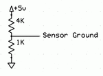
First the negative voltage part :I'm working with a 0-5v rail so I'm planning to raise the ground of sensor to 1V by a potential divider(though resistors will introduce errors). That'll bring the swing to +0.6v - +1.4 v.
Do you people have any suggestions on this ?
Second - The amplifier. In an ideal world,I would just feed it to a non-inverting opamp with a gain of around 3.
However, I've no idea what role would offset voltages would play ? Do you think they will be enough to drastically reduce the accuracy of the ADC (I need it to be about 1mv,if possible)
Can you guys help me on that please ?
I'm planning to use a LM324. I'm trying to avoid the expensive op amps as it's a low cost project and also ,if possible,potentiometers.
Any help/suggestion would be greatly appreciated !
Thank you ! :smile:
Last edited:
