Continue to Site

Welcome to EDAboard.com

Welcome to our site! EDAboard.com is an international Electronics Discussion Forum focused on EDA software, circuits, schematics, books, theory, papers, asic, pld, 8051, DSP, Network, RF, Analog Design, PCB, Service Manuals... and a whole lot more! To participate you need to register. Registration is free. Click here to register now.

Function Generator Frequency

Status
Not open for further replies.

OsmanH

Newbie level 6
Joined
Aug 11, 2011
Messages
14
Helped
0
Reputation
0
Reaction score
0
Trophy points
1,281
Activity points
1,377
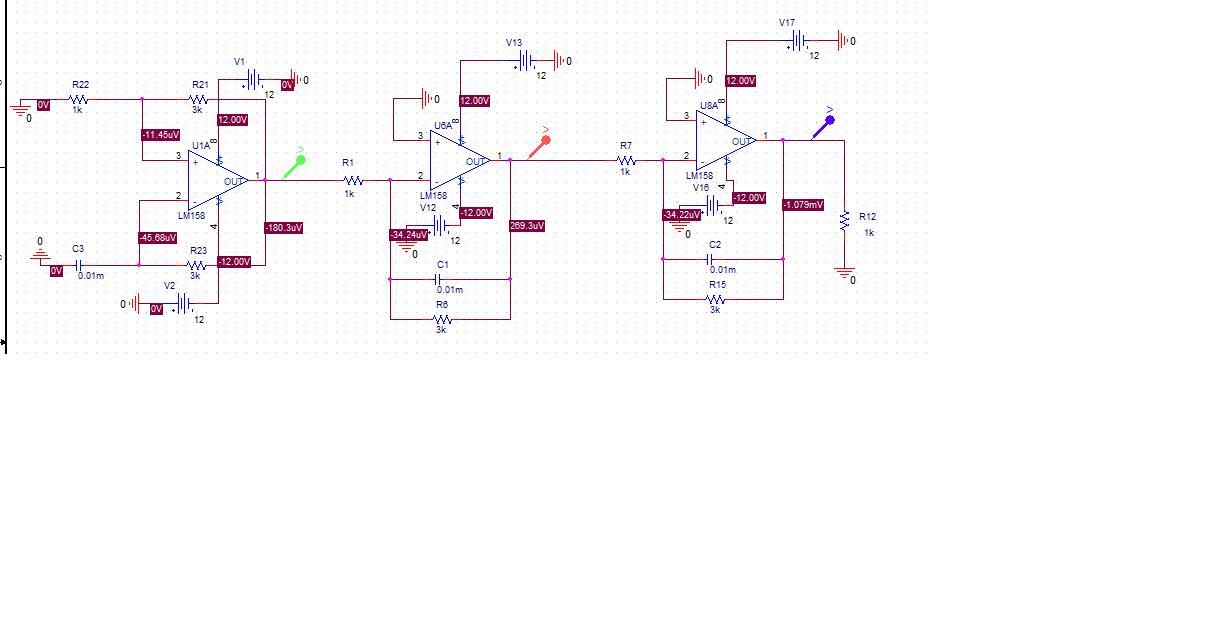
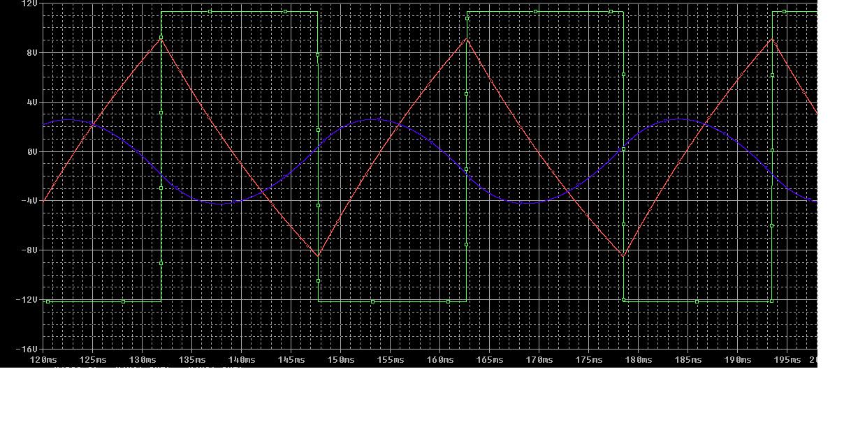
I designed a function generator that converts square wave to sine wave with using relaxation oscillator and integrators. In 30Hz ıt works properly but I want sine wave between 20KHz-30KHz. I used formula f= 1/2RCln3 for schmitt trigger but when I improve frequency I cannot get smooth waves. Can anyone help me for it?


Here is the schematic:


The circuit demands to adjust all time constants for the frequency, no only the oscillator. Did you? In my opinion, the circuit isn't well suited as a variable frequency sine generator.

In addition, the waveform quality at 30 kHz will be affected by the LM158 limited bandwidth and class B output stage crossover distortions.
 
Also, I dont know how to do AM modulation can you show me how to do it?
 

Generally, a kind of analog multiplier or variable gain element is required for AM. The available circuit options depend on your requirements for linearity, modulation depth and involved waveforms. What do you want to achieve?
 

How can I convert schematic to pcb layout can you give me an link or something
 

There are many discussions at Edaboard related to PCB design, e.g. https://www.edaboard.com/threads/218164/

Your schematic seems to be drawn by the PSpice schematic editor, so conversion to Orcad schematic and using Orcad Layout tools would be an option. It's probably better to use one of the more simple Layout tools like Eagle (small boards can be made with the free version) or some other other tool suggested in the discussion. If your project doesn't request to design a PCB, assembling the circuit on a Vero board is most likely faster.
 
I'll use Orcad Layout but I do not know steps of conversion can tell me a little if you know?

Thank you
 

Status
Not open for further replies.

Similar threads

Part and Inventory Search

Welcome to EDABoard.com

Sponsor

Back
Top