Continue to Site

Welcome to EDAboard.com

Welcome to our site! EDAboard.com is an international Electronics Discussion Forum focused on EDA software, circuits, schematics, books, theory, papers, asic, pld, 8051, DSP, Network, RF, Analog Design, PCB, Service Manuals... and a whole lot more! To participate you need to register. Registration is free. Click here to register now.

Solid State 110 Volt timer delay circuit help

Status
Not open for further replies.

MalcolmV8

Newbie level 1
Joined
Sep 2, 2011
Messages
1
Helped
0
Reputation
0
Reaction score
0
Trophy points
1,281
Location
Kansas City
Activity points
1,326
Hi Guys,

I've been trying to build a simple power up delay circuit for 110 volt skimmer/pump on my salt water fish tank. My issue is that in a power failure water levels change. The sump water level rises a few inches. When power comes back on my auto top off pump is confused and pumps extra water in and my skimmer kicks on with the wrong water level and dumps nasty collected crud back into the tank.

However if both of those items could be on their own delayed power up it would cure those issues. So when power returned if there was a 3 ~ 5 minute delay for the water levels to stabilize and go back to normal, then my skimmer and auto top off get powered back on they'd work as expected.

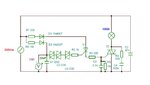
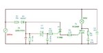
I did some googling and found this circuit in particular

Time Delay Circuit

It's for 230 volts instead of 115 which we have in the US but not a big deal. I'm sure I could make that work. However I don't fully understand that circuit and would like someone to explain it to me or show me a better circuit (or design a better one).

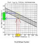
I was going to just order the parts for that one and try and build it and play around with it but I can't find the SCR 2P4M so that's when I figured I better understand what I need exactly before randomly substituting parts in.

Thanks for any pointers or advice.

Malcolm
 

Time-Delay-Circuit.png


Circuit explanation:

When you first power up your circuit, C1 starts charging up over R1. When the voltage on C1 reaches to enough level ("enough level" is the voltage that is enough to trigger the thyristor or triac. Refer to its datasheet), the thyristor conducts and starts to charge up C3. (At this point, I don't understand the function of C2. It would be good if someone else explains it.) When the voltage on C3 reaches enough level (*) the triac conducts and the load is supplied with the 230V AC.

Total time delay = Time to charge C1 to enough level (t1) + Time to charge C3 to enough level (t2)

For more information about RC charge time, refer to this page.
\[V_c = V_s \times (1 - e^{-\frac{t}{RC}})\]
You will use this equation to calculate t1 and t2. Vc is the enough voltage level to trigger the switching element. Vs is the supply voltage. This equation assumes that Vs is DC voltage level, however your supply voltage is AC. You may approximate Vs as the average value of half wave rectified 230VAC, which is about 73V. You can ignore the voltage drop on D1 and the thyristor.

For t1 (in terms of seconds);
Vc = 73V * e^(-t1 / (22kΩ * 1000µF))
(Look for Vc at the datasheet of the thyristor, and solve the equation for t1.)

Similarly, for t2;
(Value of R3 is much less than value of R2. You can ignore R3 and assume that C2 and C3 are parallel.)
Vc = 73V * e^(-t2 / (22kΩ * (470µF + 100µF)))
(Look for Vc at the datasheet of the triac, and solve the equation for t2.)

Total time delay = t1 + t2
 

The C1 capacitor will charge up gradually through the R1 resistor until the voltage across the capacitor reaches the threshold voltage of the thyristor (0.7V) . The voltage across the capacitor, VC1 at any instant in time during the charging period is given as:
VC1 = Vs[1 – e (-t/RC) ]
Vs= the peak supply voltage
If we use 230 Vac, the peak voltage is therefore 230* 1.41, which is about 325 V :cool:
Do the math to obtain 70ms time delay.

Later the triac turn on for VC2> Vgt +Igt*R3 ~ 4V
Second time delay ~ 270 ms
Total time delay = 70+270 =340ms = 0.3s

For 115Vac, Vs= 160V, total time delay ~ 100ms +600 ms= 700ms= 0.7s
So, no big deal with this time delay… need to change for another schematics.
 
Need to read the datasheet:
**broken link removed**
for example:
 

Attachments

  • 2P4M.JPG
    2P4M.JPG
    53.1 KB · Views: 81
I have tested in practice this circuit using C106M Thyristor, BT139, TIC206M, TIC216M, TIC226M, BTA16 triacs.
I have also measured and compared the illumination on a work table for the 100W light bulb. Ambient illumination =70 lux, and typical illumination for light bulb power supply direct connection =1100 lux.
Using
BT139 ~300 lux, time delay ~ 3-4 s
TIC206 ~ 1100 lux, time delay ~ 0.2-0.3s
TIC216M ~450 lux, time delay ~ 0.3- 0.5s
No success for TIC226M, BTA16.


Be careful, in this circuit time is required to fully discharge the capacitor
 

Thank you, I know the problems, that’s why not so practical using this circuit. Anyway, I have made some changes to the circuit to increase the time delay by adding some DIACs in circuit, see the diagram attached. In practice I have obtained a more large time delay due to the capacitor leakage current :roll: , and in between two timings need to wait also a lot of time for discharging the capacitor.


Attachments

  • triac delay 1a.JPG
    triac delay 1a.JPG
    59.8 KB · Views: 90
Hi Guys,

I've been trying to build a simple power up delay circuit for 110 volt skimmer/pump on my salt water fish tank. It's for 230 volts instead of 115 which we have in the US but not a big deal. I'm sure I could make that work. However I don't fully understand that circuit and would like someone to explain it to me or show me a better circuit (or design a better one). I can't find the SCR 2P4M so that's when I figured I better understand what I need exactly before randomly substituting parts in.

Malcolm

Why dont you use a NE555 timer IC based timer circuit with a relay. Parts are easily available, low cost , no voltage dropping resistor(no heat),safer to operate and handle and can be used for any AC voltage range. Delay time can be changed with a potentiometer or small preset. Search Google for IC 555 based timer.:-D

See the link for circuit, veroboard schematic etc for a 555 based timer for 1 to 10 min duration.
Adjustable 1-10 Minute Timer Project
 
Last edited:

The original circuit is better. Just put a 10K resistance parallel to the capacitor to discharge it quicker.
or try this ,
switch on delay1.jpg
 
Last edited:

No, not a single chance for this version, tested with TIC206M(see the results) and BT139… Back to the drawing board. :-D


This one will work for sure:

**broken link removed**

EDIT: Opamp inputs will be reversed.
Vref ==> Inverting input
Vcharge ==> Non-inverting input
 
Last edited:

Just updated some components values. Sometime ago i made 3-5 minutes delay_0n timers for refrigerators. I will look for its schematis and pcb.
 

Let's try this...
 

Attachments

  • AC21.JPG
    AC21.JPG
    56.7 KB · Views: 75

Status
Not open for further replies.

Part and Inventory Search

Welcome to EDABoard.com

Sponsor

Back
Top