Continue to Site

Welcome to EDAboard.com

Welcome to our site! EDAboard.com is an international Electronics Discussion Forum focused on EDA software, circuits, schematics, books, theory, papers, asic, pld, 8051, DSP, Network, RF, Analog Design, PCB, Service Manuals... and a whole lot more! To participate you need to register. Registration is free. Click here to register now.

driving a ignition coil using a transistor and mosfet

Status
Not open for further replies.

robismyname

Full Member level 6
Joined
Jan 17, 2008
Messages
390
Helped
11
Reputation
22
Reaction score
9
Trophy points
1,298
Location
Central Florida
Activity points
4,603
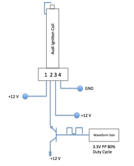
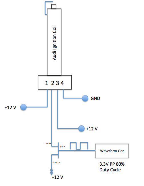
Im trying to replace a transistor with a mosfet to drive the spark of a ignition coil.

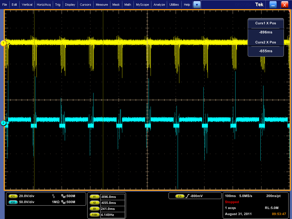
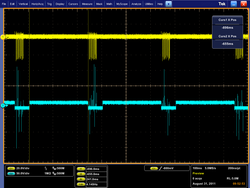
I hooked up a npn (mpsA05) to pin 2 of a ignition coil to control/switch on and off the spark from a ignition coil. The performance/results appear to be good. See attached image of circuit and waveform. channel 2, the blue signal is my square wave from the generator. channel 1, the yellow signal is the reading i took using a field probe to read the spark strength.

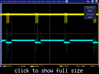
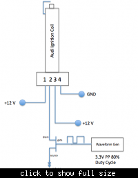
I then removed the npn (mpsA05) and replaced it with a mosfet (Si7120DN). Its not working at all. The fet does not cause the coil to spark or do anything. I dont understand why the transistor worked and the mosfet did not.

Any help is appreciated.
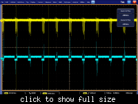
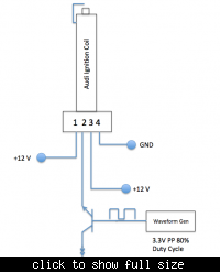


Gate source voltage is low (3.3v).increase it to 8-12V for proper switching of FET.
 

If you're going to bury that MOSFET (or BJT) you ought
to have a series resistor to avoid burning up the primary
or the switch. You probably also want a shunt cap or
snubber to avoid the flyback of the primary punching out
the switch. A properly sized one can give you a better
spark than none, if it takes the current and lets the
switch get to fully off.

Search up some DIY electronic ignition schematics
and look for those features.
 

Are you sure it is not damaged yet. It is rated for 10A but power rating is only 1-1.5 watts, which can be easily damaged by operating in linear region.
 

Your N-channel mosfet is connected wrong and is "high-side" as well.

Here is one of very many tutorials that explains those errors: Using the Power MOSFET as a Switch

In summary:
1) Source should go to ground; Drain should go to positive supply. Usually, Drain goes to load (i.e., the ground side of the load), which I also suggest you do here. That configuration is called, "low-side."
2) In "high-side", Drain goes to +12V (as you show) and Source goes to load. BUT, the gate in that case must be driven by 12V + the gate turn-on voltage. For normal mosfets, that is about 10V. Thus, your gate must be about 22V referenced to ground to work. The reason for that is that the N-channel mosfet turns on when the gate-source voltage (Vgs) is about 10 volts. If the mosfet is doing its job and there is minimal voltage drop across it, the source voltage ≈ drain voltage. Thus, in high-side, the gate must be drain voltage + 10V.

John

Edit: Why did you pick that mosfet, particularly that package?

Edit#2:

Is your Audi an A4? I did a quick search on Audi ignition to try to figure what all the connections you show did. If you have that A4 temperamental ignition, I wouldn't mess with it. Do you have any technical information about the ignition module you are using?

You mention using a signal generator. Can you give more detail about how you are driving the gate? Although it is said that the mosfet gate is voltage controlled, in order to get the gate voltage to change rapidly for rapid switching, you need to charge it with a substantial current. For example, dedicated gate drivers will provide 500 mA to several amps briefly.
 
Last edited:
Obviously, the ignition module has a built-in power stage, otherwise it would hardly work with a small-signal transistor like MPSA05. Talking of an ignition "coil" is rather misleading. The good point seems to be, that it isn't easily damaged, even if operated ignorantly. But I wouldn't rely on this strictly. For reasonable experiments, get a documentation first, as jpanhalt suggested.
 
Your N-channel mosfet is connected wrong
According to diagrame you posted, its true. Source and drain should be switched ie drain conected to +12V and source to ignition coil. Emiter follower and source follower aplication. Fet will drop 2-4 volts so its not good.
 
Last edited:

Your N-channel mosfet is connected wrong and is "high-side" as well.

I managed to get the circuit working however I am worried about the voltage spikes on the blue waveform (ignition coil) affecting my other circuitry on the board. Is there any way to reduce these spikes that are shown in the blue ignition coil waveform?
 

You don't know for sure that those trigger-pulse spikes are real. It could be
a matter of where you put the ground clip. But that brings up the point of
"which ground" and current loop management. You might go so far as to use
an optocoupler since the trigger input of the ignition module likely needs a
fairly small current. So far I recall zero detail on what the input really needs,
it seems to me you are just trying stuff without understanding that.
 

Status
Not open for further replies.

Part and Inventory Search

Welcome to EDABoard.com

Sponsor

Back
Top