Continue to Site

Welcome to EDAboard.com

Welcome to our site! EDAboard.com is an international Electronics Discussion Forum focused on EDA software, circuits, schematics, books, theory, papers, asic, pld, 8051, DSP, Network, RF, Analog Design, PCB, Service Manuals... and a whole lot more! To participate you need to register. Registration is free. Click here to register now.

How to design a photodiode circuit to get its dark current as output?

Status
Not open for further replies.

anushaas

Member level 5
Joined
Jan 4, 2011
Messages
84
Helped
0
Reputation
0
Reaction score
0
Trophy points
1,286
Activity points
1,979
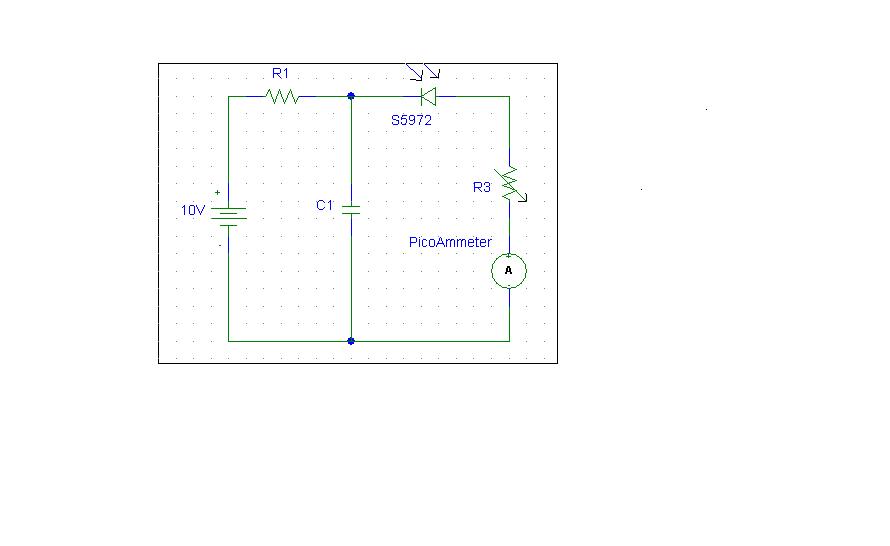
Can anyone tell me what should be the optimum values for R1,C1 and range of R3 so as to get the dark current of s5972 photodiode(from Hamamatsu) which is of pico ampere range?The sensitive area of photodiode is properly covered to avoid any kind of reflections so as to get the dark current as output.


Attachments

  • photodiode sch.bmp
    1.4 MB · Views: 89

**broken link removed**
 

Thank you.But I have gone through these materials before.They dont give an exact range of values.......
 

Please explain more. What do you want? As far as i can get you want to measure the current when there is no light and no infrared source on it?

And what is your application?
 

I can;t know for sure, but I think he's trying to make a compensation circuit for another photodiode. Then he could substract dark current signal from useful signal. Well, that is if the dark current is exactly the same amongst all of the diodes of he same type.
 

... what should be the optimum values for R1,C1 and range of R3

I think these values aren't critical at all. I'd assign R1 a voltage drop of 1V at the highest expected dark current (typ. 10pA, max. 0.5nA @ 25°C) at your highest expected temperature, say R1 = 1V/10nA = 100MΩ. With a ceramic cap of C1 = 1nF or 10nF (close between the photodiode's cathode and GND) you have a ≈1Hz low pass filter against noise and op. voltage changes.

R3 isn't necessary at all, but anything between 1..10 MΩ doesn't hurt if you insist.
 

Please explain more. What do you want? As far as i can get you want to measure the current when there is no light and no infrared source on it?

And what is your application?

I aim at designing a circuit that would generate an output current of order pA say some 10pA.This is to test an amplifier circuit that would amplify this pA current to a measurable voltage of range 0-5V.

There is no light source because I attempt to get the dark current of the photodiode s5972 which is typically 10pA according to datasheet
 

I aim at designing a circuit that would generate an output current of order pA say some 10pA.This is to test an amplifier circuit that would amplify this pA current to a measurable voltage of range 0-5V

Don't you think there are other way to generate such low current and test your amplifier. What so special about this circuit?
 

I think you maybe want something pulsed-mode, like a
CTIA (as many imager front ends use). A capacitor, a
shorting (reset) switch, and a comparator whose timeout
tells you time-to-charge. Which could just be a single
MOSFET if you can stand crude threshold (and you can
characterize that for deskew).

If you're looking for tens of pA you don't want many other
leakages bundled into your test jig.
 

I think these values aren't critical at all. I'd assign R1 a voltage drop of 1V at the highest expected dark current (typ. 10pA, max. 0.5nA @ 25°C) at your highest expected temperature, say R1 = 1V/10nA = 100MΩ. With a ceramic cap of C1 = 1nF or 10nF (close between the photodiode's cathode and GND) you have a ≈1Hz low pass filter against noise and op. voltage changes.

R3 isn't necessary at all, but anything between 1..10 MΩ doesn't hurt if you insist.

Thank you for the suggestion Sir

I tried the circuit with these resistor and capacitor values but the output current observed was in the nA range(some 3nA).What I want is current in pA range say few tens of pA.I tried varying the resistor values as well but the attainable current was of nA range.

What can be done to bring down the output current?
 

Apart from the question, if other circuits may be better suited as low current generator, why don't you use standard low leakage diodes instead of photo diodes?
 
Don't you think there are other way to generate such low current and test your amplifier. What so special about this circuit?

What could be an alternate method for generating such small current?
 

It depends some whether you need the thing to look
like a real current source, or just get the right current
at one particular operating point.

I would say to use a source-degenerated, small signal,
low noise, high quality PJFET (for sourcing current) with
a high value source resistor from which you take the
feedback to a very low leakage op amp. That will have
a pretty decent ideality.

But otherwise if you know the voltage then you could set
up an op amp with a source resistor and a replica feedback
such that an offset voltage, hence offset current is pushed.

At picoamps you can't afford much elaborateness attached
to the business end. How much of it you need, depends on
what you really want from the source.
 

How to get a picoAmp current source?

What could be an alternate method for generating such small current?

Ohm's law; you told it yourself:
I used a voltage source in the mV range along with 1 Giga Ohm input resistance so that I can get some 1 to 10 pA current input to circuit.

For the mV voltage source, use a resistive voltage divider, e.g. 5kΩ to 1Ω from a stable 5V (USB) source, together with your 1GΩ series resistance. Or 5MΩ:1Ω (1µV) with a 1MΩ series resistor.
 
Last edited:

Considering the fact, that the current source is intended to test an I/V converter with at least mV offset voltages, you surely would want to give it > 10 Gohm source resistance. In my opinion, it's quite easy to generate uncalibrated pA currents, e.g. using diode leakage currents, as suggested. The interesting point is to do it calibrated. Referring to the specification of available calibrators can give some hints.

I didn't hear a clear specification for the pA current source yet, I wonder, if it's purpose is well considered at all.
 

Apart from the question, if other circuits may be better suited as low current generator, why don't you use standard low leakage diodes instead of photo diodes?

Sir,

What can be an alternative method for such low current generation?

What I am aiming at is a very low current of some tens of pA? Could you please suggest what other standard diode will be suitable?
 

Are you going to test it in space, vacume but cosmic rays may affect there also. Ig ohm may be close to air resistance.
 
Last edited:

Don't you think there are other way to generate such low current and test your amplifier. What so special about this circuit?

What else could be an alternate means for generating such small current(of rhe order of some tens of pA) Sir?

Kindly give your suggestions.

---------- Post added at 17:28 ---------- Previous post was at 17:25 ----------

Are you goin to test it in space, vacume but cosmic rays may affect there also. Ig ohm may be close to air resistance.

But won't proper covering for the sensitive area of photodiode there by preventing reflections as well will help?
 

Hi,
If you see carefully the data sheet shows shows the DARK CURRENT at the specified diode voltage.
Photo.jpg
Photo1.jpg
 

Which is the device which will consume that current and at what voltage range?
The diode connected in reverse will not act as costant current regulator. It is not made for that purpose. Leakage current is an undesired phenomenon depend upon tepmerature and material properties. If i ask you, are you making a noise generator t hen that would be true. Diode reverse leakage is used to input an amplifier to generate noise.
See noise geneator schmatics.
34_1315940329.gif
69_1315940736.gif

Zener diodes make more noise so they are used . And see why metal oxide resistors are made and used instead of carbon resistors.
Reverse leakage current - Wikipedia, the free encyclopedia
 
Last edited:

Status
Not open for further replies.

Similar threads

Part and Inventory Search

Welcome to EDABoard.com

Sponsor

Back
Top