Continue to Site

Welcome to EDAboard.com

Welcome to our site! EDAboard.com is an international Electronics Discussion Forum focused on EDA software, circuits, schematics, books, theory, papers, asic, pld, 8051, DSP, Network, RF, Analog Design, PCB, Service Manuals... and a whole lot more! To participate you need to register. Registration is free. Click here to register now.

Keypad 4x4,3x3 circuit troubleshooting

Status
Not open for further replies.

electronicsIdiot

Junior Member level 1
Joined
Oct 31, 2010
Messages
16
Helped
0
Reputation
0
Reaction score
0
Trophy points
1,291
Activity points
1,420
HI, to all

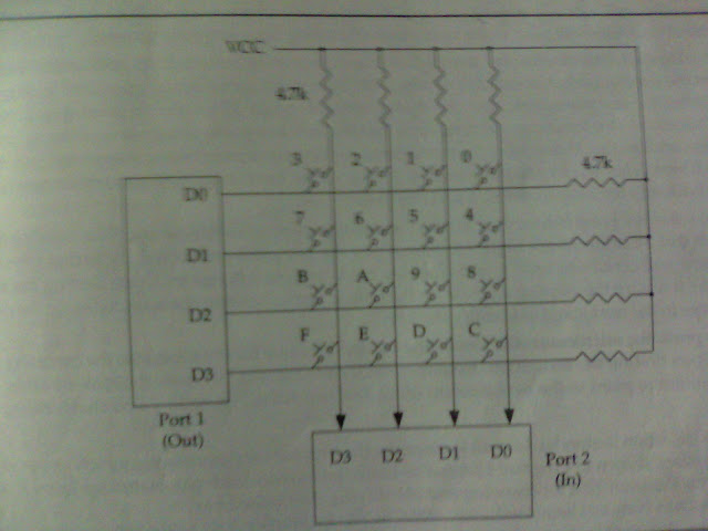
I made 2 keypads 3x3,4x4. I think I made them wrong. I want to troubleshoot the problem please guide me in that and can I do the job of keypad from only one port for input as well as output because book says to use 2 separate ports one for the input and one for the output.I think by doing all this in one port is good Idea.

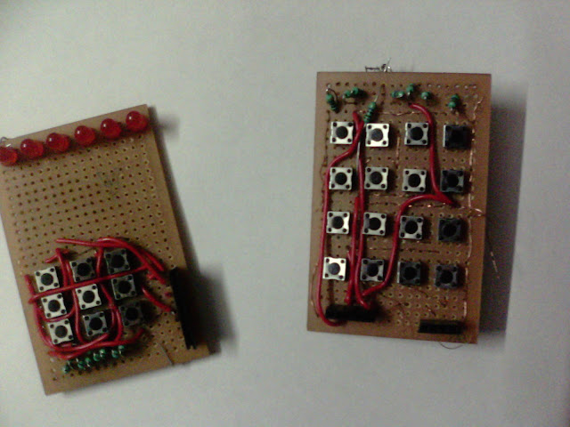
Please See: In keypad I use LED to check the button working when no key is pressed LED glow and one key is pressed the brightness increased but this is not the case for all the row and column some are give full glow and in some alternate key affect the glow

Please Help I put my whole efforts and have taken enough aroma of solder's:cry: smoke
 

Hi,

You need to show the circuit and software you are using.. is it Pic or AVR and what language ?

You can use one Port but that needs a bit more software control that using two separate ones
 

show your work, some one can sort it out
 

I have taken up the pic of the book figure and my circuitry

IMG_20110817_204552.jpg


this is my circuit I use copper thread wires because other solder joining purpose wires are limited

From back side
IMG_20110817_204518.jpg


From Front side
IMG_20110817_204505.jpg


I also found the same kind of image of the first one of my this post a website and it is text that making a keypad is simple

Matrix Keypad interfacing with Microcontrollers tutorial: : 8051 Microcontroller Projects AVR PIC Projects Tutorials Ebooks Libraries codes

The problem in the circuit

4X4


in The Front side you can see a long red wire at the left side of the PCB having no LEDs and two saperate female connector
in This column when only 2nd and
4th push button increase the brightness of LED

moving toward right the 2nd column
only the last one near the Female connector Push button works

The last 2 columns give full brightness


3X3

the Push buttons near the resistor are giving brightness change and other buttons give full brightness
The soldering of 3x3 looks horrible cause I have made some changes as Resistors are at wrong place so I remove them and keep them in the diagram order.


please help
 

Hi,

Cannot help you with the program code as I do not know AVR C, though would assume the code should work ok.

Where you have a wired board like that there is a high chance of short circuits, so before you even try and connect it to a micro you need to debug those boards.

You need a multimeter, set to ohms, preferably with the low ohms bleeper.

Without any power connected and no switches pressed, you need to methodically check for shorts between each row 1,2,3,4 and then each column 1,2,3,4.
If ok then check for any short between each row and each column.

Once thats done you then connect to Row 1 and column 1 which should be open circuit, press SW1 and the bleeper should sound.
Repeat the exercise on every row and switch.

Where you do find a short then inspect the tracks and try and find the cause.
 

hello, the program and the keypad connection from that site is working. I tested it personally using 8051..

it is the same tutorial with this site
**broken link removed**


IMG_20110817_204552.jpg

I noticed in your picture you are not doing right here. the connection of the keypad is provided in that site and it is in one PORT only

the code is provided there and this is the connection
keypad-8051-th.gif
 
Status
Not open for further replies.

Similar threads

Part and Inventory Search

Welcome to EDABoard.com

Sponsor

Back
Top