Continue to Site

Welcome to EDAboard.com

Welcome to our site! EDAboard.com is an international Electronics Discussion Forum focused on EDA software, circuits, schematics, books, theory, papers, asic, pld, 8051, DSP, Network, RF, Analog Design, PCB, Service Manuals... and a whole lot more! To participate you need to register. Registration is free. Click here to register now.

Problem with the Laplace transfer function of MFB lowpass filter

Status
Not open for further replies.

lizardno1

Newbie level 5
Joined
Apr 15, 2010
Messages
9
Helped
1
Reputation
2
Reaction score
1
Trophy points
1,283
Location
China
Activity points
1,335
i am working on some filter topologies,trying to figure out how these filters work.and in a TI's application report ,i find the MFB filter circuit
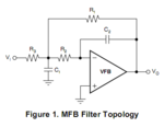
p1.PNG
the Laplace transfer function given by the document is
p2.PNG
however,the Laplace tranfer function derived by myself dosen't match the one above,and i'm really confused about it
My derivation:
step1:mark the voltage at the junction between R2 & R3 as Vt.Because Vp=Vn=gnd=0,so Vt/R2=-Vo/(1/sC2),Vt=-sC2*R2*Vo------Eq1
step2:according to KCL theory,(Vi-Vt)/R3=Vt/(1/sC1)+(Vt-Vo)/Rp,where Rp=R1//(R2+1/sC2)------Eq2
step3:solve Eq1 and Eq2 to get Vo/Vi

can anyone find which step of my derivation is wrong?thx a lot.
 
Last edited:

step2:according to KCL theory,(Vi-Vt)/R3=Vt/(sC1)+(Vt-Vo)/Rp

I did not check your calculation in detail, however, one error certainly is the conductance marked above that should be an impedance.
 
LvW,
thx for pointing out the mistake
actually,it's my typo.it should be (Vi-Vt)/R3=Vt/(1/sC1)+(Vt-Vo)/Rp,where Rp=R1//(R2+1/sC2)
and i didn't get the same answer as TI's.

regards
lizardno1
 

haha^.^
i replaced the eq2 as (Vi-Vt)/R3=Vt/(1/sC1)+Vt/R2+(Vt-Vo)/R3,then the result turned right.
but i still can't understand why i can't use the previous eq2,since there is current flowing into the negative input of the op-amp under ideal circumstances:???:
 

The error you have made with eq. (2) is as follows:

Due to feedback the inv. terminal is (nearly) at ground potential. However, your Eq. (2) simply assumes that the input is disconnected from the passive part: see your expression for Rp. Obviously, that was not correct. OK?
 
Lvw,
i think u r righti. i guess it's not correct to include two different nodes when using Kirchhoff's Law in most cases.
And i'm really appreciated for ur help:smile:
 

.. i guess it's not correct to include two different nodes when using Kirchhoff's Law in most cases.

What does this mean? Do you think that KCL applies only if one node is grounded? (...in most cases ??)
I am afraid you misunderstood the meaning of my former answer.
 

sorry. my words are confusing.i thought the wire between two component as a node just now. How ridiculous!
And i didn't misunderstand ur ansewr,i just misunderstood the KCL's Law(2 nodes,OMG...)
thx anyway,for pointing out the mistake
 

Status
Not open for further replies.

Part and Inventory Search

Welcome to EDABoard.com

Sponsor

Back
Top