Continue to Site

Welcome to EDAboard.com

Welcome to our site! EDAboard.com is an international Electronics Discussion Forum focused on EDA software, circuits, schematics, books, theory, papers, asic, pld, 8051, DSP, Network, RF, Analog Design, PCB, Service Manuals... and a whole lot more! To participate you need to register. Registration is free. Click here to register now.

Mosfet based Dc motor controlled circuit

Status
Not open for further replies.

Ashkar

Full Member level 2
Joined
Sep 16, 2010
Messages
131
Helped
2
Reputation
4
Reaction score
2
Trophy points
1,298
Location
India
Activity points
2,207
Hi all

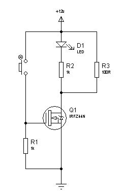
I want to know what should i do to control the speed of 5A 12V dc motor using IRF44n mosfets I want to drive it by a AVR atmega32 micro controller.So please guide me.

Supply voltage =12vdc
load =max 7A

9770-2005feb14_amd_nt03.jpg
 

Hey my friend!
you should create PWM with your micro controller at 15KHZ or higher frequency and then use this circuit:rs.JPG
you should give your pulses with an opto coupler to gate of your mosfet.
about L and C : those are integrator network
the first circuit is better
 

Attachments

  • si.JPG
    si.JPG
    58.7 KB · Views: 218
Last edited:

there into , your circuit that you attached has some problem!
you can use my circuit.
Goldsmith
 

there into , your circuit that you attached has some problem!
you can use my circuit.
Goldsmith

The schematic of the first post works fine and is actually better that the one you have provided!!!
The original schematic uses a totem pole driver to supply the gate of the mosfet a high current to charge/discharge the gate fast, this will limit the switching losses and will make switching faster and heat losses very low.

If you try to drive your circuit with the few mA that are available from an mcu and at a rate as high as 15KHz you will have overheat problems.

Alex
 

But the mosfet would require good amount of current to operate.Would a 4n35 opto would work

---------- Post added at 13:11 ---------- Previous post was at 13:06 ----------

So Alex what should I do then.I ahve build the circuit but the mosfet isn't switching off
 
The mosfet will switch off when you apply a positive voltage to the transistor input, the operation is inverted, the mosfet turns off when the input port C2 is High

Alex
 

but its'nt working in any way
 

The schematic is correct, I don't know if you have something wrong in your real circuit.
Connect manually the transistor input to 0/5v or even 0/12v , use a resistor (for example 1k) in the output instead of the motor and measure the voltage in the mosfet drain.
Also check the pin connections of all components

Alex
 

Dear Alex
my mean is not circuit is not correct but in this application and this low frequency some of elements are not important to use.
Thanks
goldsmith
 
Dear Alex
my mean is not circuit is not correct but in this application and this low frequency some of elements are not important to use.
Thanks
goldsmith

The OP intension is to control the speed of the motor and he can only do that using PWM.
When you have a PWM controlled mosfet the switching speed is very important, do you consider a switching speed of 15KHz low frequency?

This schematic was from an older post but I was trying to make the same point, how important it is to drive the mosfet correctly (the input is slightly higher at 20KHz).
The two schematics show the difference when you drive the gate with 5mA and 1A, red is input voltage and blue is output current (which has the same shape as the output voltage since the load is a resistor)
As you can see it is not possible to maintain even a 50% duty (5mA circuit) so imagine what will happen when you want 5%

mosfet_drive_compare.jpg

Alex
 

Alex as I specified to you ,my components are good but the response is strange i.e my mosfet isn't switching off.Which software do you use to simulate the circuits.;-)
another question ,If i apply a high current directly into the mosfets then does it burn the gate of it.:cry:
 

The schematic above is in Proteus.
The mosfet can only be damaged if you apply a Vgs that is above the max specification (usually about +-20v but you have to check the datasheet)
As I said in the previous post your circuit is correct, you either have a damaged component or a wrong connection


Alex
 

What alex has said is right. The circuit posted is perfectly fine. It will just invert the signal from the AVR. When the AVR gives "high" or "1", the MOSFET is turned off. The MOSFET is turned on when the AVR gives "low" or "0". The circuit in the first circuit is better than the one provided later, because it will drive the MOSFET better with more current, turning it completely on and completely off very fast. It is more efficient. The 2nd circuit drives the MOSFET from a much lower voltage than the 8-10v required to completely turn it on.

Ashkar, the MOSFET is an IGFET (Insulated Gate Field Effect Transistor). Staying within the maximum ratings of VGS, you can not drive current forcefully to burn it. However applying a voltage greater than the maximum stated VGS, you will burn it.

Hope this helps.
Tahmid.
 

@ Tahmid would you please suggest me any method to test my mosfet .

---------- Post added at 19:29 ---------- Previous post was at 19:27 ----------

@Alex I think my mosfet gates are burnt because the circuit is working fine without the fets.

---------- Post added at 19:31 ---------- Previous post was at 19:29 ----------

Is orcad a better option.
 

Try this:
5_1312828903.png


You might leave out the 100R resistor if you like.

When you press the switch, the LED should light up.

Is orcad a better option.
For what?

Hope this helps.
Tahmid.
 

For simulation of circuits.Am not much into the softwares so could you please help me suggest a good simulator.
 

Dear friends
in all circuits that you use mosfets or IGBTS or FETS you should use a resistance in parallel with gate to source . because their gate is isolated and in gate to source we have a little capacitor! if this capacitor going charge , cant going discharge and mosfet likewise will on. if you use a gs resistor(usually 39 K) you can improve it as well as!
Wish you the best
 

I would say that 39K is too high. I always use 1k. In one of Sanjaya Maniktala's books, he has mentioned how, when he used 10k resistors, his MOSFETs were getting burnt, but when he used 4.7k, the problem was fixed. I have never had problems when using 1k resistor.

Hope this helps.
Tahmid.
 

Status
Not open for further replies.

Part and Inventory Search

Welcome to EDABoard.com

Sponsor

Back
Top