ashish.mw
Full Member level 2
hello,
I am trying to model a pair of stripline transmission lines that encounters a slot in one of the metal planes using HFSS and then analyze how this affects the common and differential modes over a wide range of frequencies. I got a tutorial for this which suggests me to Set the solution type to Driven Terminal. Now when i try to place the waveport as specified by the tutorial as;
"Draw > Rectangle
First point (20, -4, -1) Size (0, 8, 2)
Under the Attribute tab, name it port1.
OK
With this rectangle selected, choose HFSS > Excitations > Assign > Wave Port.
Accept the default name and click Next.
Update to two terminals: type the number 2 in the field and click Update.
Click on “Undefined” for terminal 1, change this field to “New Line” and, using the coordinate fields at the bottom of the HFSS window, enter the vector with start point
(20, -0.9, -1) and size (0, 0, 0.95). A vector from the ground plane to trace_1 has now been defined. This helps the software to manipulate excitations.
Click on “Undefined” for terminal 2, change this field to “New Line” and enter the vector with start point (20, 0.9, -1) and size (0, 0, 0.95). A vector from the ground plane to trace_2 has now been defined.
Click Next.
Click New Pair. HFSS defines the two terminals as a differential pair, which will enable us to work with differential and common signals rather than single-ended excitations. Accept the default impedances. They mean that the lines will be terminated at the port with 100 Ohm for the differential mode and 25 Ohm for the common mode.
Click Next.
Accept the default – it means that when we obtain single-ended results, the loads at the port are 50 Ohm for each line.
Click Finish."
I am not able to follow these steps as my version of HFSS i.e. HFSS12 don't show me such options. My design picture is as follows:
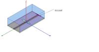
can anyone please help me how to draw the waveports in case the solution type is Driven Terminal and not Modal following the above tutorial steps in simplified manner. I shall be highly obliged.
Thanks in advance.
-Ashish