Continue to Site

Welcome to EDAboard.com

Welcome to our site! EDAboard.com is an international Electronics Discussion Forum focused on EDA software, circuits, schematics, books, theory, papers, asic, pld, 8051, DSP, Network, RF, Analog Design, PCB, Service Manuals... and a whole lot more! To participate you need to register. Registration is free. Click here to register now.

Circuit Wizard and Yenka related simulations

Status
Not open for further replies.

PG1995

Full Member level 5
Joined
Apr 18, 2011
Messages
248
Helped
1
Reputation
2
Reaction score
1
Trophy points
1,298
Activity points
3,758
Many, many thanks for the reply, Jony. It was very much helpful. It seems that my questions weren't that much stupid.:wink: If it weren't people like you I would have bade farewell to my studies long time ago!

I have downloaded trial versions of both simulators: Yenka Electronics, CircuitWizard.

CircuitWizard: Features - Circuit Wizard - Products - New Wave Concepts Limited
Yenka Electronics: Design and Technology

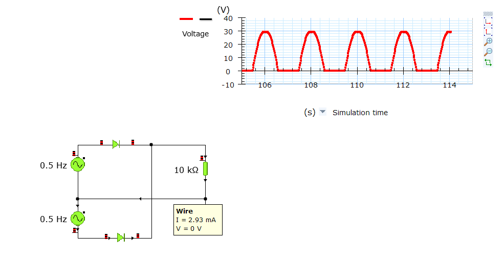
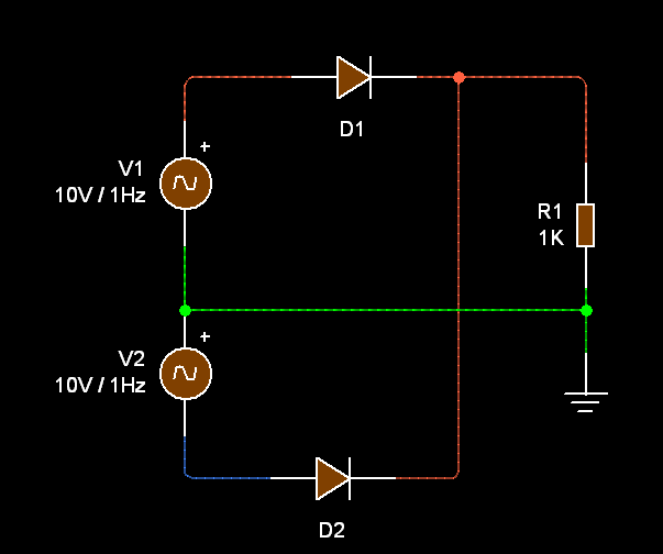
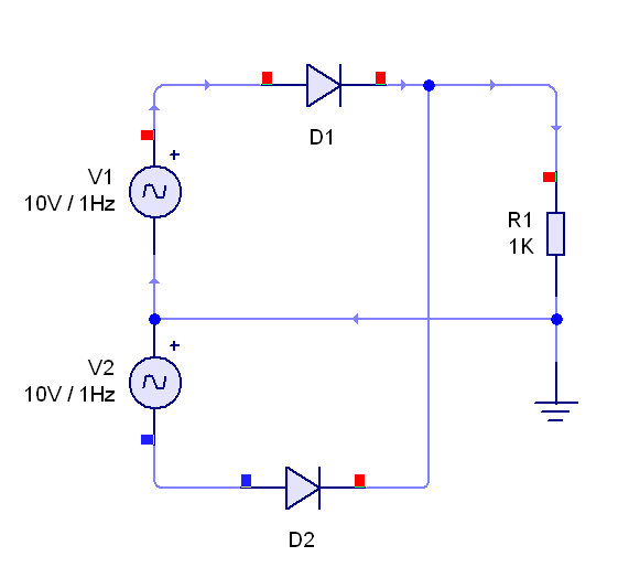
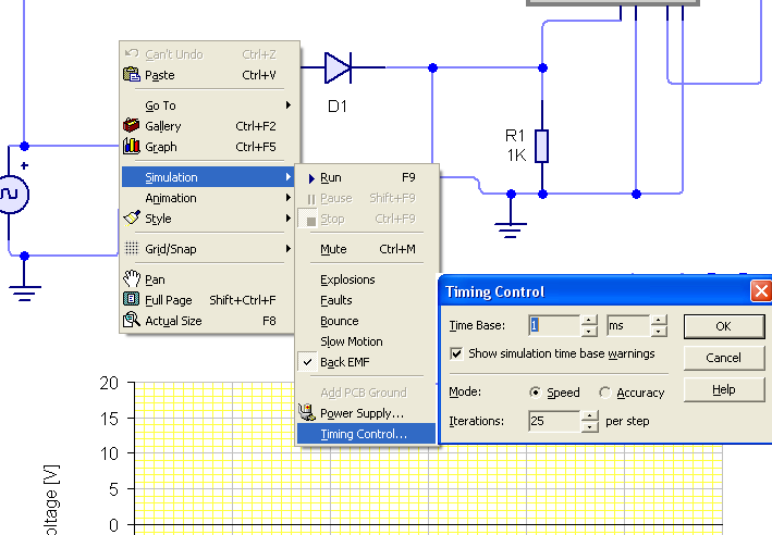
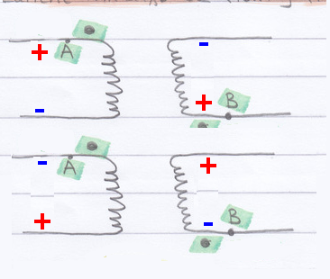
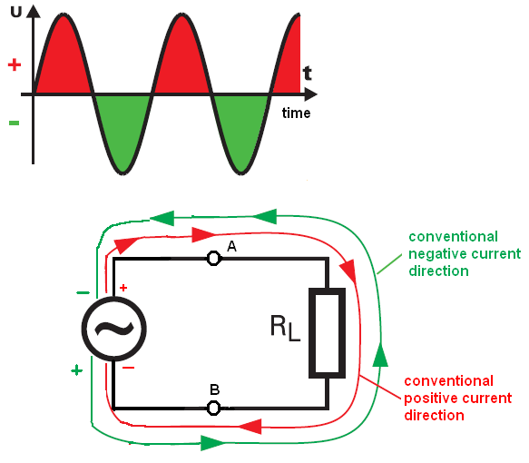
I wanted to have a simulator which shows the flow of electrons so that I can understand current is flowing through different components. Do you think If I had Yenka or CircuitWizard, then it has shown me that during positive half cycle current flows from A to B etc. concerning that transformer question above? I haven't installed those simulators yet. I watched a couple of videos on Utube about the simulators but none of the videos showed the electron flow!:???:

Best regards
PG

The previous posts of this thread were multisim related, they can be found https://www.edaboard.com/threads/217987/ [alexan_e]
 

Re: learning to use MultiSim

Look at Yenka example
The arrows indicate the direction of current and this color bars show the voltage level


And Circuit Wizard show the current path like this
 

Re: learning to use MultiSim

Thanks a lot.

I have drawn the rectification circuit in Circuit Wizard and ran the simulation. Please have a look on this video:
‪rectification circuit wizard.avi‬‏ - YouTube

You see I have set the frequency of the AC source to be 1Hz but still I can easily observe the flow of the current, so is there any way to decrease speed of simulation?

Which software of the three you prefer: MultiSim, Circuit Wizard, Yenka Electronics? Please let me know. Thanks.
 

Re: learning to use MultiSim

Open the file that I attach, I simply slow the simulation by changing the simulation time from 1s to 1ms


Sometimes I use Yenka, but I prefer to use PSpice 8.0 or LTspice.
The MultiSim and Circuit Wizard, Yenka I download only from curiosity. I'm almost don't use these programs.
 

Attachments

  • 1test.rar
    4 KB · Views: 80

Re: learning to use MultiSim

Thank you for the reply.

1: But it seems MultiSim is the most popular one out there. It's used in accompanied CD of every book etc. I was wondering why don't they introduce that current flow feature in MultiSim or PSpice?

2: Please have a look on this diagram: https://img204.imageshack.us/img204/7523/picture1cgp.jpg

The current is flowing from E to F in the primary. I have been told, as you know, that during the +ve half cycle (I mean when current is flowing from E to F), the current will flow from A to G. But it isn't. It's flowing from C to G. Why is so?

3: Please have a look on these two images:
https://img715.imageshack.us/img715/7643/crktrectcmnt.jpg
https://img696.imageshack.us/img696/6197/crktrec2.jpg

I hope you can understand my question there. Is this a bug in Circuit Wizard? You can also have a look on the following video:
‪crktrectvid.avi‬‏ - YouTube

Please help me. Thank you.
 

Re: learning to use MultiSim

1: I was wondering why don't they introduce that current flow feature in MultiSim or PSpice?
We can see the current, but in a deferent way


2: Please have a look on this diagram: https://img204.imageshack.us/img204/7523/picture1cgp.jpg

The current is flowing from E to F in the primary. I have been told, as you know, that during the +ve half cycle (I mean when current is flowing from E to F), the current will flow from A to G. But it isn't. It's flowing from C to G. Why is so?
Everything is ok, you simply forgot about dot convention.
Where you have dots in Circuit Wizard transformer?

3: Please have a look on these two images:
https://img715.imageshack.us/img715/7643/crktrectcmnt.jpg
https://img696.imageshack.us/img696/6197/crktrec2.jpg

I hope you can understand my question there. Is this a bug in Circuit Wizard? You can also have a look on the following video:
‪crktrectvid.avi‬‏ - YouTube

Please help me. Thank you.
I don't think that it is a bug.
Do you know now that there is a phase shift in an inductor between voltage and
current, right?
 
Last edited:
  • Like
Reactions: PG1995

    PG1995

    Points: 2
    Helpful Answer Positive Rating
Re: learning to use MultiSim

Thank you for the help, Jony. Unfortunately I wasn't able to fully understand what you told me because of my own very limited knowledge of this stuff, therefore I will try to rephrase my queries. I humbly request you to make your replies as simple as possible so that I can understand them. Thank you.

1:
Dot Convention: Please have a look on the following linked diagram. You will find also my question there.
https://img694.imageshack.us/img694/5194/imgzf.jpg

2:
Please have a look on the following linked scan: https://img824.imageshack.us/img824/355/img0002iy.jpg

What I think of AC current:
Let me tell you what I think of AC current. As you can see in the diagram there are two terminals A and B. e- stand for electrons and arrows stand for their direction of motion. When electrons are moving toward left of the page, the current or voltage is +ve and when electrons are moving towards right of the page the current is -ve.

I think each terminal, A and B, switches between +ve and -ve. When A is +ve, B is -ve. If frequency of AC is 50 Hz then each terminal switches between opposite polarities 100 times during one second. So, it is all about push and pull of electrons.

Please have a look here to see my questions: https://img232.imageshack.us/img232/6489/img0001qn.jpg

Supplementary material:
For Q2:
Image: https://img98.imageshack.us/img98/8125/currentchangeddirection.jpg
Video: ‪currentchangeddirection.avi‬‏ - YouTube

For Q3:
Images:
With ground: https://img232.imageshack.us/img232/2084/addingground.jpg
Without ground: https://img694.imageshack.us/img694/371/withoutground.jpg

I'm very much grateful for all your help.

Regards
PG

PS: I know how to add graph for o-scope. So, you can skip Q4.
 

Attachments

  • 1test.rar
    4 KB · Views: 72
Last edited:

Re: learning to use MultiSim

1:
Dot Convention: Please have a look on the following linked diagram. You will find also my question there.
https://img694.imageshack.us/img694/5194/imgzf.jpg
The dot convention defines the polarity of coil terminal voltages not the current.
So if we have positive voltage at dotted end of a primary winding we will have the positive voltage at dotted end of the secondary winding.
And if the dotted end of a primary winding become negative the secondary winding dotted end will also becomes negative.

16_1311606532.png


2:
Please have a look on the following linked scan: https://img824.imageshack.us/img824/355/img0002iy.jpg

What I think of AC current:
Let me tell you what I think of AC current. As you can see in the diagram there are two terminals A and B. e- stand for electrons and arrows stand for their direction of motion. When electrons are moving toward left of the page, the current or voltage is +ve and when electrons are moving towards right of the page the current is -ve.

I think each terminal, A and B, switches between +ve and -ve. When A is +ve, B is -ve. If frequency of AC is 50 Hz then each terminal switches between opposite polarities 100 times during one second. So, it is all about push and pull of electrons.
Your understanding of a AC current looks good
And remember that almost all engineers analyses their circuit assume that current flow from + side to - side. So to avoid confusion use this convention to


As for Q1/Q5 look at this imagine


So for positive swing the point A more positive in relation to point B.
And for negative swing point B becomes positive in relation to point A.

Q2

It is very strange but it seams that what you have watching is nothing but the transient state.
And when you speed up the simulation time (10ms) and increase the load resistance 100R everything is back to normal (we have steady state after 500ms).

And you have to remember that current in the primary winding contains two components.
The first one is the magnetizing current and the load current.

So when the load current is small compared to the magnetizing current the current in the primary winding will be 90° lagging behind induced voltage.
And as you should know the voltage across the coil is proportional to the rate of change in current
V = L * dI/dt

15_1311617500.png


But you will learned about coils and transformer operation in the in the future.

Q3

Well, once again you forget about GND .


Without a reference point (GND) simulation will show wrong result.
To measure the voltage you need a reference point for your measuring instrument (see 3test).
 

Attachments

  • acb.rar
    8.4 KB · Views: 57
Last edited:
  • Like
Reactions: PG1995

    PG1995

    Points: 2
    Helpful Answer Positive Rating
Thanks a lot, Jony. It was very helpful. But I would need more help with the Q2. I haven't read about inductors; will read about induction tomorrow and will then make my queries.

I wanted to ask that if it is possible to convert MultiSim circuits into Circuit Wizard circuits.
 

This change in current direction (for 2.5V) (phase-shift) was cause by transient state in the transformer primary winding.
In normal condition (steady state, file 2test, XSC2 show the primary winding current) when the load current is is greater than magnetizing current there is almost no phase-shift between the primary current and voltage.


The green trace show the primary winding voltage
And the blue trace show primary winding current.

But when load current is smaller then magnetizing current, we will have the phase shift between the primary voltage and current.


And this phase shift is cause by primary winding inductance

47_1311624032.png
 

Hi again,

I know that CW has an o-scope with very limited functionality. But it doesn't even draw a graph in my case. What do I do to make it work for me? Please let me know. Thank you.

circuitwizard_inductor.avi - YouTube

Best wishes
PG
 

Attachments

  • learninginductor.rar
    3.7 KB · Views: 101

Here you have the simulation. To reach steady state you need to wait at least 2.5s simulation time.
 

Attachments

  • learninginductorx.rar
    4.1 KB · Views: 99

Thanks a lot, Jony.

Could you please tell me how you activated that o-scope graph so that next time I can do it myself?! :)


Best wishes
PG
 

Status
Not open for further replies.

Part and Inventory Search

Welcome to EDABoard.com

Sponsor

Back
Top