Continue to Site

Welcome to EDAboard.com

Welcome to our site! EDAboard.com is an international Electronics Discussion Forum focused on EDA software, circuits, schematics, books, theory, papers, asic, pld, 8051, DSP, Network, RF, Analog Design, PCB, Service Manuals... and a whole lot more! To participate you need to register. Registration is free. Click here to register now.

Problems when simulating a simple analog integrator in Pspice

Status
Not open for further replies.

waynesuvol

Newbie level 5
Joined
Oct 9, 2010
Messages
8
Helped
1
Reputation
2
Reaction score
1
Trophy points
1,283
Activity points
1,375
Hi everyone!

I am now trying to simulate the behavior of a conventional analog integrator in Pspice.
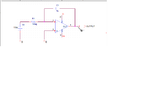
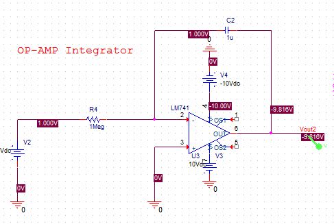
The circuit is simple, capacitor in the negative feedback loop around the ideal opamp. I attach the schematic.
I use a DC source as the input of the integrator. I just want to see the output of the opamp integrating with the constant.
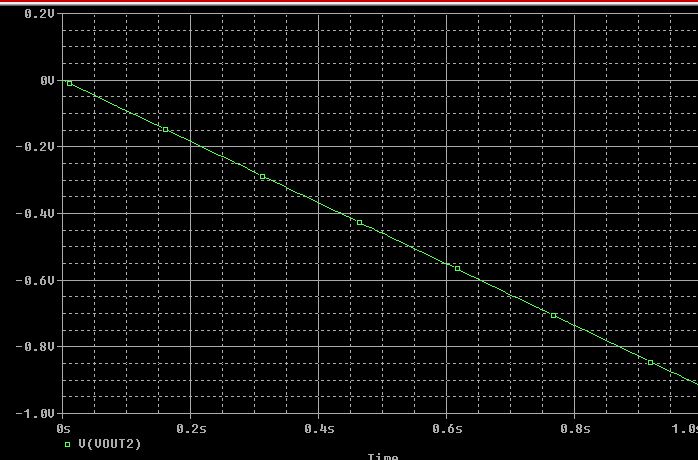
BUT, the simulation result is very disappointing. The output of the opamp is clipped at the negative power supply. But what we expect is a ramp.
Is this result caused by the algorithm used by Pspice? There shouldn't be anything wrong with the circuit because it is too simple. I think it must have something to do with the method that pspice uses to solve the circuit. Please help !! Thanks a lot!!!
 

Attachments

  • Untitled.png
    Untitled.png
    26.9 KB · Views: 442

Your result is normal.

Let us assume there is no capacitor.

What would you expect to see at the opamp ouput?

Kerim

Edited:
I assume you already know how an opamp works.
And this was the first step to find out how to get the ramp at its output (since we apply a constant voltage, hence the charging current is also constant in C1).
 
Last edited:

Hi Kerim,

Why the result is normal? The capacitor should be charged, right? But no charging happens......
The DC operating point simulation showed that, the voltage of inverting input terminal is not near ground. It is equal to the input voltage......too bad....
This should be something related to how Pspice extracts the matrix of the circuit, I think. But I really do not know why...
 
Last edited:

Why the result is normal? The capacitor should be charged, right? But no charging happens......

How it can be charged if the initial voltage of the opamp output is already at its lowest value V-.

The DC operating point simulation showed that, the voltage of inverting input terminal is not near ground. It is equal to the input voltage......too bad....

How can the inverting input be close the ground? As you know the resistance (impedance) of the opamp input (negative or positive) is very high, it is like an open circuit. So obviously it has to be equal to the input voltage (1V).

This should be something related to how Pspice extracts the matrix of the circuit, I think. But I really do not know why...

Pspice has nothing wrong :smile:
Please, I noticed that you didn't answer my previous first question.
Let us assume there is no capacitor. What would you expect to see at the opamp ouput?
To understand what is happening we have to go on step by step... only then all will look to you very logical :wink:

Kerim

Note:
I use the free (and professional) simulator 'LTspice'. I hope your simulator will have similar functions mainly the setting of the initial value of some voltages and currents of interest.
 
Last edited:

Note: When calculating the bias point solution, PSpice treats capacitors as open circuits and inductors as short circuits. And this is true for most of the SPICE simulator.
based on above for following circuit


You will get 1V (equal to input Voltage at -Ve input terminal of Opamp)
The initial bias values are also shown in above picture.
by default most of the SPICE simulator shows you steady state result. hence you get a flat line for O/P voltage. if you want to see a RAMP or true transient you can do so in PSpice using one of the following two

Add Initial condition to any node or capacitor. This will force simulator to skip the "BIAS point calculation" and you will get RAMP
or turn on "Skip bias point analysis" option in your simulator setting.
By using either of these methods I get the following results


Hope this explains.
 
Add Initial condition to any node or capacitor. This will force simulator to skip the "BIAS point calculation".
Not exactly. SPICE will still calculate an initial solution that fulfill the given initial condition. In most cases the result will be different from skipping bias point calculation. Tos tart with a discharged capacitor, an initial condition for the voltage accross the capacitor has to be set.

Skipping bias point is in fact an easy way to see the intended waveform. Thinking more generally, no real integrator cicruit will work without a reset means. You can e.g. place a time controlled discharge switch.
 
  • Like
Reactions: garm and LvW

    LvW

    Points: 2
    Helpful Answer Positive Rating

    garm

    Points: 2
    Helpful Answer Positive Rating
waynesuvol, If I am not in error you didn't mention what kind of analyses you have tried up to now.
Did you speak about dc or TRAN analysis? Only the latter can give meaningful results as the integrator integrates versus TIME!

---------- Post added at 10:07 ---------- Previous post was at 09:54 ----------

Remark: Contrary to KERIMF I am convinced that your simulation arrangement can work! That means: You will see the expected ramp. Only in case of a real amplifier model the offset voltage (together with the delay inside the real model) will drive the opamp into saturation
 

I'm really wondering, why they made that "calculate initial DC condition" option default in all SPICE-like simulators. Anyone knows that?
This causes whole lot of problems - because in reality *NO* circuit starts from its operating point. E.g. some oscillating circuits might not start in the simulator, unless you set the initial condition for capacitors / inductors.


Pspice has nothing wrong

There are lots of things wrong with PSpice and other *spice simulators. The unchecked by default "skip initial DC solution" option is one of them. A poor numerical engine that almost hadn't change for the past 30 years and that cannot *guarantee* convergence nor estimate numerical round-off errors properly is another one (however it is not the case here).
 
Remark: Contrary to KERIMF I am convinced that your simulation arrangement can work! That means: You will see the expected ramp. Only in case of a real amplifier model the offset voltage (together with the delay inside the real model) will drive the opamp into saturation

I forgot to mention that - in case you want to integrate a step function (starting at zero) - you must of course (!!) apply at the input a step function (and NOT a dc voltage that is used to find the bias point - in this case without success due to lack of dc feedback).

---------- Post added at 12:58 ---------- Previous post was at 12:49 ----------

I'm really wondering, why they made that "calculate initial DC condition" option default in all SPICE-like simulators. Anyone knows that?
This causes whole lot of problems - because in reality *NO* circuit starts from its operating point. E.g. some oscillating circuits might not start in the simulator, unless you set the initial condition for capacitors / inductors.
There are lots of things wrong with PSpice and other *spice simulators. The unchecked by default "skip initial DC solution" option is one of them. A poor numerical engine that almost hadn't change for the past 30 years and that cannot *guarantee* convergence nor estimate numerical round-off errors properly is another one (however it is not the case here).

One of the good reasons to calculate the dc operating point at first is the ac analysis.
What are you doing if you want to calculate the gain of a BJT amplifier? As a 1st step you try to calculate the bias point in order to find the proper transconductance. A simulator does nothing else!

I must confess to disagree with your opinion "There are lots of things wrong with PSpice and other *spice simulators"
Can you give some examples? According to my experience in 99% of all errors the cause of the problems was on the user side. Thus, don't blame the engine.
Again, I like to repeat a good example: An opamp with POSITIVE dc feedback will find in Spice a stable bias point and shows an ac gain magnitude value as expected for negative dc feedback. Is the simulator wrong? No ! The user is in error by expecting something else.
 

If you specify the .IC on a node or apply IC on capacitor or inductor, it usages that value as initial bias solution. Yes I do agree that result can be different when you have IC vs "Skip Bias.." and this would depend upon circuit. In this circuit both solutions would match.
 

Hi LvW... I think I am not fit for forums where speed counts. If you noticed, I asked him a simple question to test what he knows. He didn't answer so I assumed the case is postponed or perhaps closed, to me in the least. To enjoy teaching or learning, there must be two players I guess :)
 
Hi Kerimf!

Thanks for your advice!
I am really sorry for the late reply because I live in U.S. So there is time difference between us... I was sleeping when you were discussing the questions...Sorry for that!
For the question you asked me
Let us assume there is no capacitor. What would you expect to see at the opamp ouput?
The output should be "V+ minus V-" * Open-loop-gain, and in my case where an ideal opamp is used, the output would be saturated at one of the voltage supply rail.
The problem is that, I am not familiar with how SPICE works. Spice can give you the expected results only when you obey the rules.
It seems that for transient simulation, a correct DC operating point is very important. Without a correct operating point, transient simulation is meaningless. Is this right?

---------- Post added at 15:35 ---------- Previous post was at 15:29 ----------

Hi atripathi !

Thanks for your reply!
Yes, I agree with you that setting the correct bias point is very crucial to get the correct behavior for the transient simulation.
In my opinion, Spice is not really good at doing the dynamic simulation, i.e. transient simulation, of the system. We have to do some tricks to fool the SPICE program to get the best result.

---------- Post added at 15:42 ---------- Previous post was at 15:35 ----------

Hi LvM,

I want to do the transient simulation of the circuit, i.e. I want to see the dynamic behavior of the integrator.
atripathi 's post on the #5, in my opinion, gives a good solution to my question.
So, when doing the transient simulation of circuit, we really have to care about the starting point (bias point or initial condition) of the circuit.

Hi waynesuvol,

I think some additional comments are necessary.
It is not true that you have "to do some tricks to fool the SPICE program". I don't know if you have read my contributions from today. As I have mentioned, in 99% of all cases the user is in error not spice!.
To be specific: You want to integrate a step function in order to see the ramp vs. time.
Why don`t you specify the circuit exactly like this? That means, to apply a step function that starts at 0 sec?
Instead you connect a dc source that is NOT switched-on at a certain time. Nobody would do this in reality!
And what makes Spice during a tran-analysis? It calculates the dc operating point (because this is wise and logical for most of the circuits). However, in your case it finds a dc voltage at the input and cannot find a suitable bias condition due to missing negative feedback.
Now comes your "trick" into the game. Of course you can command Spice not to calculate the bias point before starting the simulation. And this may lead to a result that satisfies you.
But note: This way is neither logical nor gives it correct results because in reality no circuit starts signal processing from exactly zero volts. No transistor amplifier will give reasonable simulation results after disabling the bias point calculation.
I like to emphasize: This approach may work in your case because of (ideal) bias conditions of zero volts. But it is not realistic. More than that, it must not give any cause to blame the simulator. The fault is on your side!
(I mean: on the users side - not especially YOU! Sorry)
Regards
LvW

---------- Post added at 17:08 ---------- Previous post was at 17:03 ----------

To make it clear: There is no necessity "to set" the bias point. If you specify the circuit as well as the simulation commands correctly, the program does it automatically and realistic!
 
Last edited:
Hi LvW!

Thanks for your comments!
I strongly agree with you! Problems come when people are not familiar with the SPICE program! So, if we want to play the games, we must obey the rules!
Thanks again!
 
Hi LvW!

Thanks for your comments!
I strongly agree with you! Problems come when people are not familiar with the SPICE program! So, if we want to play the games, we must obey the rules!
Thanks again!

OK, I agree.
However, I am afraid with "...obey the rules" you probably are referring to some "mystic" or "tricky" or simulation specific "secrets". I am pretty sure that this is not the right sight.
The only rule is: Treat the simulator (that means: schematic entry and simulation commands) as you would do in reality!
In reality, an active circuit with real components and units (don't use ideal opamp modules, for what purpose?) is powered to achieve the wanted bias conditions and then excited with a signal source. Exactly this should be done during simulation - and you will get correct and realistic results (perhaps with very few exceptions).
In your case: What do you expect from an ideal opamp wired as an ideal integrator and excited with constant dc voltage?
In contrary, I real integration unit with a real opamp model and real power lines, which is excited with a signal source (and not with a constant source) will give you a lot more information that can be transferred to practical applications.
Regards
LvW
 

A reset switch is what's needed, on the feedback cap.
The results you got seem entirely reasonable given the
inputs.
 

The output should be "V+ minus V-" * Open-loop-gain, and in my case where an ideal opamp is used, the output would be saturated at one of the voltage supply rail.

Sorry... and even if there is no time difference, I try to always remember that any of us may not be able to reply rather quickly. That is why I used the word 'postponed' in my previous post... assuming you might be busy :)

I think you agree with me that your answer is wrong since we have here a well defined circuit with its sources (after removing C1).
Just to be sure that we think alike here is what I mean:

V2 (IN-) = 1V
V3 (IN+) = 0V
Therefore:
V2 (IN-) > V3 (IN+), and the output V1 knows very well at which supply rail should be saturated.
You were right, V1 = V- (or close to it)

Let us continue to the next step and bring C1 back while the circuit is running.

A capacitor means a storage device (like a battery if you like). So we can't be sure if C1 still has some charges in it or not. In case there are, there would be a voltage on its two terminals.
Since you as I like that everything is well defined, we try to be sure first that Vc1 = 0V (In practice, we discharge it through a resistor, or by shorting it if you like high current spikes :twisted: ).

Now we have an opamp with:
V2 = 1V
V3 = 0V
V1 = V- (I hope you agree that V+ = - V- = 5V to get numerical results later, otherwise let me know your choice)
And C1, with an initial voltage of 0V, will be added between V1 and V2 (yes, we are now watching a real test ;-) )
What will happen?

(1)
You found out in advance that the steady voltage of C1 when you first simulated the circuit is V1-V2, that is:
Vc1 = -5 - (+1) = - 6V
Here we assume that the opamp output is of rail to rail type (otherwise the output V1 would be a bit higher as -4.7 V for example).

(2)
Therefore when C1 is placed between V1 and V2, the circuit starts to charge it from 0V to -6V. But what is about the charging current from t=0 to infinity?

Well, as soon as C1 is in place, V1-V2 becomes 0V (much like if we place a small empty battery of 0V).
Fortunately this insertion helps the opamp to leave saturation and be in the linear region. I guess you know why. The reason is that at t=0 V1=V2=1V which means the ouput V1 is no more saturated and the opamp can restore its full control on its three terminals (V2, V3 and V1). We know when the opamp is linear V2 becomes close to V3 (due to the very high gain), and here V3 = 0V so yes... V2 which was 1V follows quickly (say at t=0.00000001 :) ) its brother IN+ and be close to 0V too. But V1-V2 at this moment is 0V (forced by C1), the output had no choice but to be 0V too. All this will happen at time 0 :grin:

(3)

To be continued...

(3)
Now we have:
V1=V2=V3=0 and the opamp is linear since its output is not saturated.
Also V4 (the input source) = 1V
Therefore a ‘constant’ current can pass in the resistor R1 from V4 to V2:
I(R1) = (V4-V2) / R1
I(R1) = (1 - 0) / 1e6 = 1e-6 A

At node V2, the sum of currents should be zero and since the opamp input current is negligible:
I(C1) = I(R1) = 1e-6 A
Where I(C1) is the current from V2 to V1.

And, as you know, the voltage on C1 starts to rise, based on:
Vc(t) – Vc(0) = I(C1) * t / C1
And since Vc(0) = 0
Vc(t) = I(C1) * t / C1 = V2 – V1

But as long the opamp output is not saturated, V2=0 in this circuit, so:
V1 = - I(C1) * t / C1 = - 1e-6 * t / 1e-6
V1 = - t , a very nice looking result :)
But this can’t last for too long because V1 has a lower limit at -5V which means after 5 sec the opamp will lose again its control on (V1, V2 and V3).

(4)
After the first 5 seconds, V1 has no choice but to stay calm at -5V and V3 is glad with its stable connection to ground hence V3=0.
But V2 has to quit now its brother (at IN+) and follow the rules of its surroundings instead (that is R1 and C1).
The nodes at V4, V2 and V1 form a simple RC circuit so the voltage on C1 will continue to rise but based on the general exponential formula:
Vc(t) – Vc(0) = [ Vmax – Vc(0) ] * [ 1 – e^(-t/RC) ]
Where
Vc(0) = 5V
Vmax = V4 – V1 = 1 – (-5) = 6 V
That is:
Vc(t) = [ 1 – e^(-t) ] + 5

So after the first 5 sec:
Vc(t) = V2 – V1 = [ 1 – e^(-t) ] + 5
Where:
V1 = - 5 V
Therefore:
V2 = [ 1 – e^(-t) ]

And for t = infinity
V2 = 1 V as expected

(5)

To be continued...


General note:
My intention is to present what is happening in real step by step, which may remind us what we learnt on each component and how it works. I believe a simulator can help much better if one already knows how his circuit runs in general if real. That is why I started with a real circuit here. But I also agree that this way is seldom recommended in the today's very fast world :grin:
 
Last edited:

My intention is to present what is happening in real step by step, which may remind us what we learnt on each component and how it works. I believe a simulator can help much better if one already knows how his circuit runs in general if real. That is why I started with a real circuit here. But I also agree that this way is seldom recommended in the today's very fast world.

That's basically O.K. I also agree, that it may be necessary to look at the exponential capacitor charge behaviour in saturated case, e.g. when analysing overload recovery behaviour of an integrator. For high speed circuits, you may need to continue this considerations with internal OP nodes. It's however somewhat off-topic related to the original question "how to operate an integrator in a SPICE simulation" and the underlying "how to operate an integrator in real hardware".

In so far I think, the contributions referring to reset switches and step voltage input waveforms are rather hitting the point. Besides special simulation means like skipping bias point and setting initial conditions, the most straightforward way is to operate the integrator like the real hardware is required to.
 

Hi FvM,

I have to confess that I use to be confused how to help others in forums mainly if they are students who had rarely the chance to see the real world beyond words. So I usually try not to explain words by other new words or give pre-made solutions. I do this because I believe the askers can, with some efforts, get most of them by searching or by visiting a forum.

And here is a more important confession. While most people in the world don’t mind to run while alive much like machines among which data keep transferring back and forth, I always hoped to meet a human being who enjoys discussing the subject of interest with no limit. But on the other hand, I admit that every forum has its own rules and I have no intention to break any of them.

So please let me know whenever I am doing something real wrong.
For example, in this thread I am just at the end of step (4) and I am not sure how many steps are left to explore this basic circuit (real and simulated) :oops:

For instance when I was a student and let us say I had 100 hours to study 10 chapters of a new course. I used to keep analysing, for about 40 hours, every detail in the first chapter and whatever could be related to it from all my previous studies. The second chapter would take me just 20 hours, the third 10 hours and the remained ones 5 or 4 hours only. But since my classmates know very well how to divide 100/10 they would gave 10 hours for each chapter. :grin:

In any case, I think it is easy to skip a post if posted by KerimF. And if it has something wrong, it should be deleted or corrected... And in all cases it will be okay for me and without the need to blame anyone.

Kerim
 

In any case, I think it is easy to skip a post if posted by KerimF. And if it has something wrong, it should be deleted or corrected.
It should be neither skipped nor corrected or even deleted. It's instructive in any case.

In the present thread, I think however, that the original question can be answered clearly and effectively. This doesn't exclude to analyze further effects in detail. Referring to the original situation, the exponential capacitor charging doesn't take place, because the simulator ignores all time constants for the initial bias point calculation. So the -ve OP input get's 1 V from the start.
 

Status
Not open for further replies.

Part and Inventory Search

Welcome to EDABoard.com

Sponsor

Back
Top