Continue to Site

Welcome to EDAboard.com

Welcome to our site! EDAboard.com is an international Electronics Discussion Forum focused on EDA software, circuits, schematics, books, theory, papers, asic, pld, 8051, DSP, Network, RF, Analog Design, PCB, Service Manuals... and a whole lot more! To participate you need to register. Registration is free. Click here to register now.

Problem with very low frequency oscillation.

Status
Not open for further replies.

emsensors

Junior Member level 3
Joined
Jul 16, 2011
Messages
29
Helped
0
Reputation
0
Reaction score
0
Trophy points
1,281
Location
Iowa
Activity points
1,563
This is killing me - I am at my wits end with this awful problem - somebody please help! I have some instrumentation that excites a differential coil (one drive, two symmetric pick-ups). The coil is at the end of a 50 ft. cable. There is a preamplifier also at the end of the cable that amplifies the signal from the two pick-up coils and then has a differential line driver to reduce noise back to the main unit. Back at the base station, an instrumentation amplifier amplifies the differential signal then there is a filter, more gain, phase detector, integrator, offset subtractor and amplifier and finally another low-pass filter. The whole thing runs at 10 kHz. Sometimes things are fine for days and then every now and then this very low-frequency oscillation takes hold (under 1 Hz) and can be quite dramatic and completely swamps my signal. Then it goes away and everything is back to normal. I have looked at EVERYTHING. Mostly I thought it was a problem with the driver but I finally resorted to buying a cheap audio power amp from Walmart and I still get the same behavior. Thought it was some kind of motorboating but no amount of rerouting powerlines and adding decoupling seems to help. Maybe some kind of positive feedback in the cable due to coupling between drive and the detector lines?? This is now a quite complicated system so I don't expect anybody to tell me what's wrong but if somebody could give me a hint or idea as to something new to look at..... anything, please!! Thanks.
 

Your drive and detector cables - do they share any common screen or conductors because the charecteristics of cable has a temperature coefficient and it could be that change in the ambient temperature could be altering the cables phase charecteristic enough for the phase angle to go positive. The other thing is that your operating frequency is 10^4 times that of the oscillations, is there any hi-pass/band pass filtering to reduce the amount of noise pick up in the signal leads?
Frank
 
Last edited:
Thanks for your comments. The drive is transmitted using a shielded twisted pair with the shield grounded at the instrument end. The differential return signal is transmitted in a similar manner. I need to check how the shield is attached - haven't looked at that for a while. I guess that there could be a wiring mistake in the cable - I will check that out. The return signal is low-pass filtered. I have tried an isolation amplifier and transformer but still get the oscillations! Thanks!
 

Can you draw up a simple schematic of your system? That will help us understand your setup better.
 
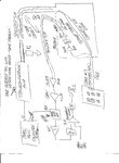
Okay, here is a sketch - sorry it is a bit rough but I have to run off to meet the wife. Will try to do a better one later. Thanks, Marcus.
 

Attachments

  • system.jpg
    system.jpg
    362.2 KB · Views: 90

The description isn't clear, I think. Do you see the low frequency signal after demodulation? How about the 10 kHz modulated sensor signal? Any interferences visible here? If some what kind? In carrier magnitude or phase? 1 Hz base band?
 
Yes, after detection. There is a lot of gain in the system so it is very hard to say if the signal is present earlier, especially so as it is so intermittent. I guess I could use a lock-in on the sensor signal and record the amplitude and phase over time. Probably should have done that already! Thanks.
 

Status
Not open for further replies.

Part and Inventory Search

Welcome to EDABoard.com

Sponsor

Back
Top