Continue to Site

Welcome to EDAboard.com

Welcome to our site! EDAboard.com is an international Electronics Discussion Forum focused on EDA software, circuits, schematics, books, theory, papers, asic, pld, 8051, DSP, Network, RF, Analog Design, PCB, Service Manuals... and a whole lot more! To participate you need to register. Registration is free. Click here to register now.

parallel transformer with piezoelectric loads impedance matching

Status
Not open for further replies.

xeratule

Member level 4
Joined
Apr 4, 2009
Messages
69
Helped
1
Reputation
2
Reaction score
1
Trophy points
1,288
Location
Istanbul / TURKIYE
Activity points
1,975
Hi,

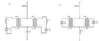
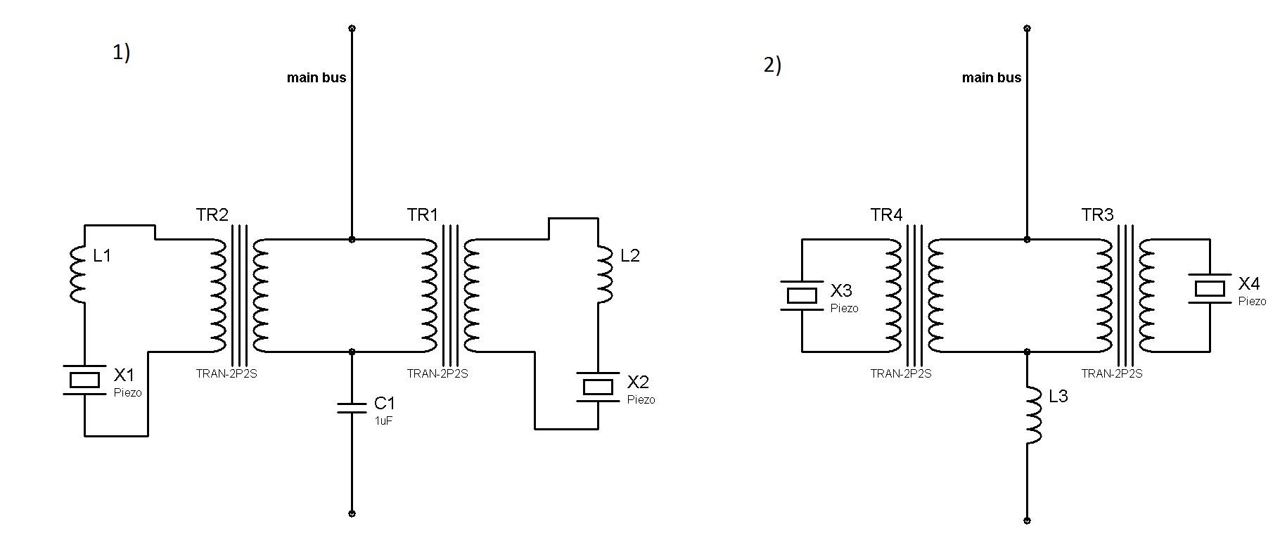
I want to match two piezoelectric transducer which are at the secondaries of two parallel transformers. I can match them while adding series inductor (series resonance) to the piezos at the secondaries of the transformers. What I want is to match them with one inductor series to the transformers. Please see the attached image. I can do the first configuration and it works fine. Could second configuration do the same job too?

In the first configuration the series capacitor to the tranfsormers (C1) is to compansate the leakage inductance of the transformers. In the second configuration I need to calculate both the leakage inductance and capacitive effects of the piezoelectric transducers and select a suitable inductor (L3) to match them both. If achievable how could I calculate L3?

ps: the main bus is high power @ 25khz pwm

 
Last edited:

In the first configuration the series capacitor to the tranfsormers (C1) is to compansate the leakage inductance of the transformers.
Exact compensation is only a special case. Generally the combination of all circuit elements decides about matching.

In my view, it's a simple AC network, but you have to know the parameters. You can decide for the second circuit, but depending on the transformer parameters, the additionally required compensating element will be either an inductor or a capacitor.
 

Thanks FvM I thought so but I don't know how to evaluate the parameters yet. Could you suggest me a method?

Orson could you please clarify what Tx and you're trying to explain is? What I understood is atransformer with one primary winding and two secondary windings for each piezo, am I right? If so, I think winding space between the ferrite and former is not sufficient enough to wind them both.
 

Why not have one Tx with a winding for each piezo?
You can also ask, why there are two transformers at all? But nothing has been said about dimensioning details yet.
I don't know how to evaluate the parameters yet. Could you suggest me a method?
Measuring the input inductance with output open and shorted. Either with a LCR meter or supplementing a series capacitor and determining resonce frequencies. You can use an equivalent circuit of your choice, e.g. L1, L2, K12 (referring to the SPICE transformer model), or Ls, Lh and ratio, whatever seems appropriate.
 

You can also ask, why there are two transformers at all? But nothing has been said about dimensioning details yet.

Because one transformer mechanical dimentions so power capacity is not enough to handle all the power.
 

Could primer or seconder winding of a transformer used as inductor? I mean I want to create inductor myself to do the calibration instead of using fixed values. Or is there a better solution?

When I remove the air gap of the transformers (T1 and T2) and connect a resistive load to the secondaries the circuit can drain 4A of currents at 220V %50 pwm. When I change the resistive load with piezo and do the impedance matching with another transformer primary winding (used as inductor) the circuit starts to operate unstable. After I increase voltage to 150V or more, the current drained suddenly jumps to higher values. Does this mean a saturation on transformer?
 

After I increase voltage to 150V or more, the current drained suddenly jumps to higher values. Does this mean a saturation on transformer?
The AC flux won't change when varying the air gap in a first order. Using the transformer leak inductance in a series resonant cicruit with the piezo can however increase it in resonance. You should have calculated a sufficient margin to saturation flux when designing the transformer.

DC flux in a circuit without primary capacitor is a different thing. It strongly depends on the air gap.

I don't exactly understand your concept of using "primary or secondary winding as an inductor". What do you mean with calibration in this regard? There's a parallel (main) and series (leakage) inductance. An equivalent circuit involving all elements should help.
 

Please see configuration 1 in my first post, but erase TR2,L1,X1.
What I meaned is piezo has some capacitive effects. I match this capacitive effect connecting series inductor to piezo. Calibrating meaned matching. I created that inductor (L2) using another E-E ferrit core which is same as TR1 transformer but different number of winding. Forget about primary or secondary as there is only one winding in L1, I think that confuses the issue.

max flux density of core is 4100 Gauss @ 90°C

I did some calculations about core loss density and from the frequency-flux density loss-power loss curve. I found operating frequency flux is 1800Gauss. I did some calculations using following formula and found the number of windings.

N = (V*ton*10^8) / (2*Ae*B)

B= flux density (Gauss)
V = 220V
ton = 0.5 * (1/25000) as operating at 25khz and with %50 duty cycle. (ton in seconds)
Ae = core area (cm²)
N = number of primary winding

is'n this calculation enough to provide enough margin to prevent saturation? Or how could I calculate saturation limits?
 

is'n this calculation enough to provide enough margin to prevent saturation?
The calculation is basically correct (CGI unit T hace replaced Gauss some decades ago, but I know it). A peak flux of 180 mT involves some losses, but should be still acceptable. As I already mentioned, the actual transformer voltage can be higher than the caculated inverter output due to the series resonant circuit. Measuring the actual primary and secondary voltage is the most easy way to get an idea about it.
 

The transformer is actually is a load to h bridge. So although DC voltage is 220V could we say the AC voltage on transformer is 440V? (But If so, it would have also saturated for the resistive load too.) The windings of primary and secondary is same. And measurements show that the voltage doesn't exceed the eventual value on primary.

However, could the inductor saturate too? ( the E-E ferrite core that I use as inductor) I have air gap in this one to have the matching value to the piezo. If I don't use air gap on this one, I should keep the number of turns too few which will probably saturate.
 

could we say the AC voltage on transformer is 440V
It's 440 Vpp, but that's not used for transformer calculation.
However, could the inductor saturate too?
The voltage across the inductor and number of windings matters, the same as for a transformer
 
Status
Not open for further replies.

Similar threads

Part and Inventory Search

Welcome to EDABoard.com

Sponsor

Back
Top