Continue to Site

Welcome to EDAboard.com

Welcome to our site! EDAboard.com is an international Electronics Discussion Forum focused on EDA software, circuits, schematics, books, theory, papers, asic, pld, 8051, DSP, Network, RF, Analog Design, PCB, Service Manuals... and a whole lot more! To participate you need to register. Registration is free. Click here to register now.

My Bench Supply Just Died - Repairs?

Status
Not open for further replies.

iceblu3710

Member level 3
Joined
Aug 10, 2009
Messages
61
Helped
1
Reputation
2
Reaction score
1
Trophy points
1,288
Activity points
1,955
I have an awesome bench power supply from the 80's that just made a funny noise then slowly faded away. Now when I turn it on the voltage meter spikes then slowly settles and then the power LED faded off. I would love to fix it but this is a complex piece of analog circuity I can now wrap my head around!

What I would like to do is understand the system so I can make a new one out of more modern components. With the large selection of low Rds MOSFETS I can make one that puts out way less heat and has a larger voltage and current range. However step one is to figure out whats going on. I understand that node (G) outputs a voltage in proportion to the selected voltage via R2/R3 and that when the current rises above the set level the current part of the circuity will lower the voltage at node (G). With the way schematics "should" be drawn I think I can assume that everything left of Q105 handles the voltage and everything on the right handles the current. From here thought I have no idea how to start analyzing the circuit.

Anybody feeling up to a challenge and willing to help me figure things out? Thanks!
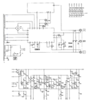
PSU_Schematic.png
 

I have looked at the circuit and pose a question :- There is a relay that changes taps on the transformer to save power consumption - have you checked its contacts, they are operating under an ardorous conditions and might be burn't out.
Frank
 

Thanks for the reply,

I have checked the contacts and they seem fine. Was able to get the replay to change states with another PSU and contact resistance was very low as expected. I think I blew a transistor as all the other passives look just fine.

Care to help me understand how the circuit works?
 

The PSU has two DC supplies, the first the main output, have you got DC volts across C102, should be 1.4 X 22 or 44 volts. There is a another supply for the regulator its self, the volts across C101 should be 1.4 X 30 V*. The terminal Q should be a couple of volts higher then the voltage the PSU is set to. If C3 or C4 are short circuit then the PSU will go into current limit and its output will be 0V, try disconnecting them and see if the voltage returns.
* the regulator DC supply sits on top of the main power supply so if you use the -ve terminal as your common, then if the DC output is 5V then the negative of the regs PSU will be 5V and its positive, 5 + 42 = 47V
Frank
 

I removed C3 & C4 from the terminals and now the PSU turns on. When I move the current limit anywhere from zero the voltage output spikes up to 100% (~22V). I removed terminal (H) from the rest of the wires on the (+) output lug and then I can adjust the current from 0-100% and the ammeter moved but the voltage on the output does not change.

C102 = 42V
C101 = 33V
(Q) = 38.5V

I would put the circuit into a spice model so I can play with things and learn but its very complex and I have not been able to get a netlist finished.
 

Most likely problem in a 31 year old power supply are the capacitors. If they are electrolytic type, they may have failed. Try replacing those with brand new ones (not surplus ones). Next I would look at the power transistors and see if they are alive. A working transistor will have a base to emitter volatage of somewhere in the 0.6 to 0.8 v range. Anything else, and it is probably blown up.
 

I spent the week metering voltages at transistors and caps and every time I turn the unit on I get voltages ranging a good 4-7V different at components and sometimes even over their ratings. This PSU was defiantly into the epic fail portion of its life so I am not even going to bother fixing it.

I would love to figure out how it works though still. I was making a spice net list but the system did not work as I do not have models for the transistors on my board and don't know how to make my own transistor models from datasheets. I would do it by hand on paper but theirs so many components I will spend a month doing math before I figure the simple things out. Can someone give me a walk through on the general operation of the PSU so I know what areas do what and can focus on figuring out those specific areas and actually learn something?

Thanks!
 

Status
Not open for further replies.

Similar threads

Part and Inventory Search

Welcome to EDABoard.com

Sponsor

Back
Top