Continue to Site

Welcome to EDAboard.com

Welcome to our site! EDAboard.com is an international Electronics Discussion Forum focused on EDA software, circuits, schematics, books, theory, papers, asic, pld, 8051, DSP, Network, RF, Analog Design, PCB, Service Manuals... and a whole lot more! To participate you need to register. Registration is free. Click here to register now.

Comparator circuit design needed

Status
Not open for further replies.

asimzia

Newbie level 3
Joined
Dec 27, 2010
Messages
3
Helped
0
Reputation
0
Reaction score
0
Trophy points
1,281
Activity points
1,305
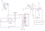
I am using 2 stage amplified load cell signal. First amplification from AD624 and then from non-inverting op amp. Now i need to compare it with a threshold.
But the problem is that when i give amplified output into the comparator, the change in weight on load cell does not affect the output of amplifier rather it remains constant.
Why it happens ?
 

loadcell.jpg

This is the circuit diagram
thanx Keith
 

From that diagram the first problem I see is that your pin numbers of the 741s don't make sense and the power on the second one is only 5V whereas you are comparing it with a voltage close to 10V... and the power supply pins are reversed on the second 741 compared to the first (but neither seem correct - there aren't 11 pins on a 741).

Keith.
 

Status
Not open for further replies.

Similar threads

Part and Inventory Search

Welcome to EDABoard.com

Sponsor

Back
Top