Continue to Site

Welcome to EDAboard.com

Welcome to our site! EDAboard.com is an international Electronics Discussion Forum focused on EDA software, circuits, schematics, books, theory, papers, asic, pld, 8051, DSP, Network, RF, Analog Design, PCB, Service Manuals... and a whole lot more! To participate you need to register. Registration is free. Click here to register now.

Frequency dependence in veriloga module

Status
Not open for further replies.

lukegeorge

Newbie level 3
Joined
Jun 29, 2011
Messages
4
Helped
0
Reputation
0
Reaction score
0
Trophy points
1,281
Activity points
1,320
Dear all,

I'm new to this forum and also in the veriloga module design.

I'm trying to design a veriloga module in which I have to impose a simple Vin/Vout behavior, and I need to impose the frequency dependence in the law. I made something like this:

Code:
module my_device(in,out);
	input in;
	output out;
	voltage in,out;

	parameter real f = 100.0;

	real vout,vin;

	analog begin
		vin = V(in);
		vout = vin * f;
		V(out) <+ vout;
	end
endmodule

When I try to assign the f parameter (frequency) equal to freq in AC simulation inside ADS Schematic I got the following:

Improper frequency dependence in 'my_device' parameters.

What I'm missing ?

Thanks in advance,
Luke
 

Dear,
thanks for the reply.

I don't understand what you mean with the use of the Laplace function. I only have the Vin/Vout behavior in the frequency domain.

Is there a way to systematically add the frequency dependence via parameter or other ?

Thanks,
Luke
 

I was able to write a veriloga module in which I had the implicit reference to the frequency

Code:
 V(out) <+ laplace_nd( V(in), {1}, {1,1/sin(freq_p1)} )

but I'm still tied to the Laplace transform to handle the frequency. Is not possible to treat frequency as simple variable ? Like If I already have the frequency domain expression for the Vin ?

Thanks,
Luke
 

Last edited:

Dear,
thanks for the response and for posting the links.

I read carefully your post about the use frequency as variable in SP simulation, but I still didn't understand the correct use of the frequency. I try to explain better my problem.

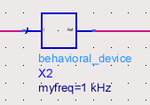
I created a veriloga module and I created a two-port schematic to handle the device. In File --> DesignParameters, I used the following settings Model: Built-in Component, Simulate As: behavioral_device (that is actually the name of the va module). Then in the tab Parameters I added a variable myfreq, Real value, Parameter Type: Frequency.

This is the actual expression I have to model (MATLAB). The vout depends on the voltage input and the frequency. This is a behavioral model and the frequency is treated like any other variable. I know this sounds weird, but for the moment this is my purpose: try to understand the behavior of the model.


Code Verilog - [expand]
1
2
3
4
5
6
7
8
9
10
11
12
13
14
vout = 1.012951e-02 - 5.467839e-04 * (1i*(2+freq)) + 2.945357e-02 * (1i*(2+freq))^2  + 4.125639e-03  * vin - 8.450533e-03   * (1i*(2+freq))^3  + 3.018920e-03  * vin  * (1i*(2+freq))[/CODE]
 
This is my va module:
 
[syntax=verilog]module sumo_filter(in,out);
    input in;
    output out;
    voltage in,out;
 
    parameter real myfreq = 1M from (0:inf);
 
    analog
        V(out) <+ ...;
endmodule


If I insert the new device in a schematic and if I perform an AC simulation the frequency is swiped only if it is inserted in a laplace expression (see in the previous post). Otherwise the module takes the default value for the var "myfreq". Notice that in the schematic AC simulation I'm only able to put myfreq = 1KHz.

Screenshot-1.png

if I try to set myfreq=freq (AC simulation) I got the error


Code Verilog - [expand]
1
Improper frequency dependence in 'behavioral_device' parameters.


Thanks,
Luke
 

but I still didn't understand the correct use of the frequency.
I try to explain better my problem.
It is not needed at all.

Your problem is simply due to lack of your very basic knowledge about Transfer Function and AC-Analysis.

Totally you can't understand very basic theory of Transfer Function at all.
And you also can't understand AC-Analysis at all.

vout = 1.012951e-02 - 5.467839e-04 * (1i*(2+freq))
+ 2.945357e-02 * (1i*(2+freq))^2
+ 4.125639e-03 * vin - 8.450533e-03 * (1i*(2+freq))^3 + 3.018920e-03 * vin * (1i*(2+freq))
Simply replace "1i*freq" with "s/(2*pi)" on your transfer function.
Then apply it for Laplace function in Verilog-A.

BTW, I think coefficients of your Transfer Function are complex not real number.
Do you want to evaluate complex filter ?
If so, you have to treat it by two real transfer functions.
Do you understand AC analysis is for real system not complex system.

On the other hand, Control System Tool-Box of MATLAB can treat complex transfer function directly.

If I insert the new device in a schematic and if I perform an AC simulation
the frequency is swiped only if it is inserted in a laplace expression (see in the previous post).
Otherwise the module takes the default value for the var "myfreq".
Notice that in the schematic AC simulation I'm only able to put myfreq = 1KHz.
Again you can't understand AC-Analysis at all.

If you want to evalaute transfer function at one frequency,
you have to set such frequency in AC-Analysis controler not instance parameter like "myfreq".

Again surely read https://www.edaboard.com/threads/202948/

BTW, I don't think Verilog-A is mandatory for your purpose.
If you want to use "freq" variable directly to express Transfer Function, use following not Verilog-A.
Hybrid (2-Port User-Defined Linear Hybrid) - ADS 2009 -*Agilent EEsof Documentation Center
 
Last edited:

Status
Not open for further replies.

Similar threads

Part and Inventory Search

Welcome to EDABoard.com

Sponsor

Back
Top