poorchava
Advanced Member level 1
- Joined
- May 21, 2009
- Messages
- 429
- Helped
- 71
- Reputation
- 142
- Reaction score
- 71
- Trophy points
- 1,318
- Location
- Wrocław, Poland
- Activity points
- 4,780
I'm currently designing a laboratory signal generator. I've already designed the generation block which can output quite clean sine wave at frequencies up to 20 MHz. Same with power supply, offset setting, and output forming (square, triangle, saw).
My problem concerns amplitude adjustment. While measuring amplitude should be fairly easy (done something like that before, just lower freqency), regulating it is another matter. My generator outputs a 2 Vpp sine wave which i intend to adjust in range of 0.1V to 15V.
My first approach was to use some kind of integrated variable gain amplifier, preferably with digital drive, but these IC's tend to cost truckloads of money and my budget is kind of tight right now. I've been thinking about placing 3 or 4 voltage dividers switched by relays for coarse adjust of generator output amplitude and then feeding that attenuated signal to the circuit as below:
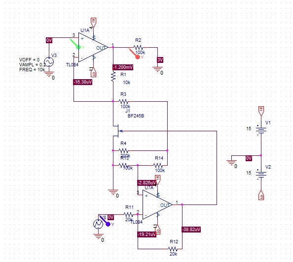
This circuit is generally an opamp in a non-inverting configuration with one of the feedback resistors replaced with a JFET. Since jfet's characteristic isn't linear i've added a circuit that linearises jfet's characteristic. According to THIS a good way to linearise a jfet is to add a 1:1 voltage divider between ground and input signal and use the midpoint of that divider as base voltage for jfet gate drive. The bottom opamp fulfills that role adding certain voltage to the midpoint potential of a divider and driving the jfet's gate with that voltage.
Now goes the question: do you see any obvious flaws in this design? (apart from part symbols - I've used some generic opamps just to check the idea in simulator at lower frequencies) Maybe u have some suggestions how to impreove it or an alternative solution?
Thanks in advance
My problem concerns amplitude adjustment. While measuring amplitude should be fairly easy (done something like that before, just lower freqency), regulating it is another matter. My generator outputs a 2 Vpp sine wave which i intend to adjust in range of 0.1V to 15V.
My first approach was to use some kind of integrated variable gain amplifier, preferably with digital drive, but these IC's tend to cost truckloads of money and my budget is kind of tight right now. I've been thinking about placing 3 or 4 voltage dividers switched by relays for coarse adjust of generator output amplitude and then feeding that attenuated signal to the circuit as below:
This circuit is generally an opamp in a non-inverting configuration with one of the feedback resistors replaced with a JFET. Since jfet's characteristic isn't linear i've added a circuit that linearises jfet's characteristic. According to THIS a good way to linearise a jfet is to add a 1:1 voltage divider between ground and input signal and use the midpoint of that divider as base voltage for jfet gate drive. The bottom opamp fulfills that role adding certain voltage to the midpoint potential of a divider and driving the jfet's gate with that voltage.
Now goes the question: do you see any obvious flaws in this design? (apart from part symbols - I've used some generic opamps just to check the idea in simulator at lower frequencies) Maybe u have some suggestions how to impreove it or an alternative solution?
Thanks in advance