Continue to Site

Welcome to EDAboard.com

Welcome to our site! EDAboard.com is an international Electronics Discussion Forum focused on EDA software, circuits, schematics, books, theory, papers, asic, pld, 8051, DSP, Network, RF, Analog Design, PCB, Service Manuals... and a whole lot more! To participate you need to register. Registration is free. Click here to register now.

Understanding circuit working

Status
Not open for further replies.

electronicsIdiot

Junior Member level 1
Joined
Oct 31, 2010
Messages
16
Helped
0
Reputation
0
Reaction score
0
Trophy points
1,291
Activity points
1,420
My First Robot 2 transistor based line follower
DSC02633.JPG


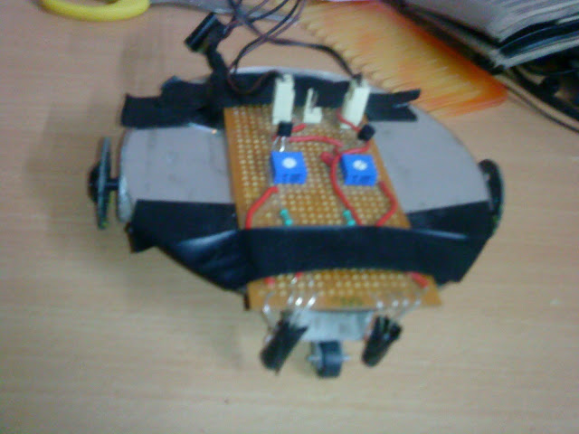
completed by following ermicro website but it works when battery weight is not added to it i.e. battery on hands and make it offload.
I also made a two 555 timer based siren.

I want to know how these circuit works.Do i need to apply kvl, kcl and Network Analysis :shock: on them

what i know at this time is:

for robot
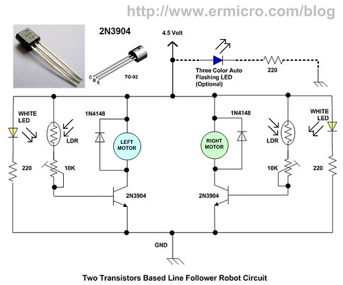
Transistor amplify(by beta 100 for 2N3904 and 800 for 2N2222) the base input(if it enough to get amplified) from LDR then motor will start rotating and potentiometer are speed controller.
and also transistor are in linear region as stated in blog
and the base act as a valve
circuit:
3709205059_6476ae5f05.jpg

for siren

**broken link removed**
exact circuit link is lost but the timer have a trimpot of 10k and 100 k,but my question is for any kind of circuit

555 timers works in astable multivibrator
and RC network gives time delays as well as different frequency(fall on sound frequency).
i noticed one(timer+potentiometer) is for frequency and one for periodicity.

mathematicallly it is a time constant.
and the siren makes funny sound

I can make circuit to be exist in real world
but don't know how to design by myself.
 
Last edited:

In realistic and useful electronic circuit, the input can be decomposed into two separate components:
-DC component, VI
and
-small signal component, vi(t)
The DC component signal is not a function of time, but the small-signal component vi(t) is a function of time (this signal is an AC signal).
This signal vi(t) is referred as the small-signal component because its magnitude is generally small for all time t.

The purpose of DC analysis is to establish a Q-point (quiescent point) or DC operating point. The goal is to set the Q-point such that it does not go into saturation or cutoff when an ac signal is applied. If the Q-point is in active region, the transistor can operate as an amplifier.

The purpose of AC analysis is to obtain the gain (ratio of output voltage and input voltage).
..........................

The DC Analysis of transistor circuits involves solving for all (or most of) the currents and voltages in the circuit. The most important DC parameters to solve are Ic and Vce. There is a definition called the “Q-point” of a transistor, which is simply the Values of Ic and Vce that are present in the transistor circuit. So if you are ever asked to find the Q point of a transistor, solve for Ic and Vce.
Here are the two fundamental bipolar transistor equations for linear circuit analysis (everything we do with bipolar transistors is based on) :

Ic = β * Ib The collector current is controlled by the base current
Ie = Ib + Ic The emitter current is the sum of the base and collector currents


There is a parameter called β (Beta) for every transistor, which is a constant. The basic mathematical model of the BJT is a current controlled current source. A current between the base and emitter terminals controls a current between the collector and emitter terminals. The name for the control factor is beta. The value of β for transistors is normally between 50 – 500(or more).
Equation Ic = β.Ib states that the collector current is β times bigger than the base current. Hence β is simply a ratio between collector and base current.
.................................

AC analysis is pretty tricky, but with a good understanding of the principals and a bit of practice it's easy.
Find the AC equivalent circuit by replacing all capacitors by short circuits, inductors (if any) by open circuits, dc voltage sources by ground connections and dc current sources by open circuits. Transistor can be redrawn for small-signal AC analysis.
You need to choose a model for the BJT transistor, as for example ''Hybrid-Pi small-signal model'' (but there are other models equally).


At the end combine the results of dc and ac analysis (superposition) to yield the total voltages and currents in the circuit.

..............................

There are plenty of examples on the net :

https://www.ittc.ku.edu/~jstiles/312/handouts/Example DC Analysis of a BJT Circuit.pdf
Transistor Amplifiers - The Common Emitter Amplifier


For the first diagram I noticed that you already understand how it works.
Bipolar Junction Transistor (BJT) is designed to operate as the current gainer amplifier. The transistor collector current passed through the DC motor will varying according to the base current which controlled by the LDR (Light Dependent Transistor) and 10 K trimmer potentiometer (trimpot). Therefore the current through the DC motor will vary according to the light intensity received by the LDR.
In practice may be necessary to introduce a system of gears (between the engine and wheels) that make the gear ratio to increase power at low speeds.

As for the diagram that uses the 555 series circuits, maybe you need to check the data sheets in order to know how the circuits works and learn how to combine them obtaining various effects/ timings ...

Read here:

**broken link removed**
 
Last edited:
  • Like
Reactions: yello

    yello

    Points: 2
    Helpful Answer Positive Rating
Status
Not open for further replies.

Similar threads

Part and Inventory Search

Welcome to EDABoard.com

Sponsor

Back
Top