Continue to Site

Welcome to EDAboard.com

Welcome to our site! EDAboard.com is an international Electronics Discussion Forum focused on EDA software, circuits, schematics, books, theory, papers, asic, pld, 8051, DSP, Network, RF, Analog Design, PCB, Service Manuals... and a whole lot more! To participate you need to register. Registration is free. Click here to register now.

[SOLVED] Help me by checking if this PCB would work

Status
Not open for further replies.

Hest

Junior Member level 1
Joined
Jun 14, 2011
Messages
19
Helped
0
Reputation
0
Reaction score
0
Trophy points
1,281
Activity points
1,436
As a new pcb designer, I'm not totally sure that what I do will always work. I have made a couple of boards and would like to have them made soon.

I have made my boards from schematics found on the net and I would like if someone could check this one for me and tell me if it's correct or not.

My board is a "police flasher" with a NE555 and a CD4017 and it should go like this O = flash, _ = off:
O_O_O_O_restart

One thing I'm not sure about, when doing the reset on the CD4017, will it immediately go to OUT#0 or will it have an empty "tick" before it starts again?

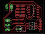
Here is the board and the schematic I used for designing it. Would this work and do you have any tips on how to test a design like this?
police-flasher.jpg

diagram.jpg
 

Re: Would this pcb work?

It is recommended to tie the LM555 pin 4 to pin 8 and connect a capacitor (100nF) between pin 5 and pin 1. Doing this will make it more reliable although it should work without them.
It is also a good idea to connect a capacitor (10uF) across the + and - supply rails for the same reason.
You will only get low LED brightness as the CD4017 is not intended to be a current driver, perhaps that's what the BD135 is intended for.

The PCB looks OK, assuming it is all SMD except the capacitor. As a general rule, if you can 'flood fill' the remainder of the board with copper and attach it to the -ve rail it would be considered good practice and it means less copper has to be removed so it uses less etching chemicals.

Brian.
 
Last edited:
  • Like
Reactions: Hest

    Hest

    Points: 2
    Helpful Answer Positive Rating
Re: Would this pcb work?

Thank you, do you know if there is a way to fill the empty areas with copper in Eagle or is it only the manual way?

I'll try to fit the capacitor's if that can make the timer more stable. It's ment to fit in small model cars, so I'm going for as small as possible :)
 

Re: Would this pcb work?

Hest,

This circuit is a simple one. Why don't you try it out on a breadboard to test this out?

I agree with betwixt's suggestions to make the PCB perform better as his suggestions improve EMI, decoupling and grounding.

1 more thing. I suggest you widen the trace width of the VDD, so it works better (lower resistance, hence lower IR drop on your supply rail).
If you want to flood-fill, do it for your GND (ground) as it is a good common practice.

Cheers!
 
  • Like
Reactions: Hest

    Hest

    Points: 2
    Helpful Answer Positive Rating
Re: Would this pcb work?

Found out how to fill the board. Eagle has so many functions, I probably don't know half of it yet. Also added the the 100nF and connected pin 4 and 8, so it's starting to look good.

In the how do I change the speed of the flashing? Isn't that R2 and C1?

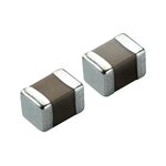
And would it be possible to change the "large" 10uF on the board image, with a SMD type like this one or does it have to be the other round type?
450077_BB_00_FB.EPS_1000.jpg
 
Last edited:

Re: Would this pcb work?

High pulse width is determined by R1, R2 and C1.
Low pulse width is determined by R2 and C.
Easier and practical to vary resistor than capacitor, so I suggest you change flashing speed by varying R2.
You can use a trimmer 10k and it is easily available.

For 10uF, use round through-hole type (easier to find in few pieces) as it is easier for you to manual solder.
SMD type usually comes in tape and reel, so not easy for you to get in loose pieces.
 

Re: Would this pcb work?

For 10uF, use round through-hole type (easier to find in few pieces) as it is easier for you to manual solder.
SMD type usually comes in tape and reel, so not easy for you to get in loose pieces.

But would it work if I used them instead? Size matters when I'm building it into a small truck and the capacitor might get to high.
 

Re: Would this pcb work?

It still works. Doesn't matter if you prefer to use SMD type or through-hole type.
If you find 10uF a little big, you can use a smaller capacitor like 1uF and bend it down 90 degree flat lying on the PCB.
 
  • Like
Reactions: Hest

    Hest

    Points: 2
    Helpful Answer Positive Rating
Re: Would this pcb work?

Thanks for all your help :)
 

Re: Would this pcb work?

@Hest,

I assumed you were talking about using a SMD ceramic 10ufd, not electrolytic. SkyHigh's comment about soldering was probably intended for the SMD electrolytic types. They are just a little more difficult to solder, but still easy. The SMD ceramic is quite easy to solder. It will also give a flatter board.

So, I would go with the SMD like you show. BTW, I assume you considered that the typical mounting of SMD's is on the side opposite through hole components (i.e., the copper side). TH components can be soldered to the copper side, but it can be a little more difficult. In more advanced PCB's, you have to be careful of the mirroring that some programs automatically do for you when you intend to mount TH IC's and such on the copper side.

John
 

Status
Not open for further replies.

Part and Inventory Search

Welcome to EDABoard.com

Sponsor

Back
Top