vinodstanur
Advanced Member level 3
- Joined
- Oct 31, 2009
- Messages
- 751
- Helped
- 114
- Reputation
- 234
- Reaction score
- 114
- Trophy points
- 1,333
- Location
- Kerala (INDIA)
- Activity points
- 7,054
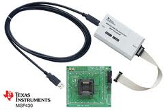
I got a couple of this MSP430F5438IPZR 16-Bit Ultra-Low-Power
Microcontroller, 256KB Flash,
16KB RAM, 12 Bit ADC, 4 USCIs,
32-bit HW Multi) microcontroller from Texas as free samples. I have some experience with pic16f only. Then i am really impressed of the features of this microcontroller, feel its really excellent.
But,
now i am in doubt how to start with it. Even i dont know how to solder that to a pcb. Is there any IC socket available for there type of microcontroller?Because first time i am going to use an SMD. Any one have any previous experience with this microcontroller? And , which c compiler is used for this texas micros?

16-Bit Ultra-Low-PowerMicrocontroller, 256KB Flash,
16KB RAM, 12 Bit ADC, 4 USCIs,
32-bit HW Multi) microcontroller from Texas as free samples. I have some experience with pic16f only. Then i am really impressed of the features of this microcontroller, feel its really excellent.
But,
now i am in doubt how to start with it. Even i dont know how to solder that to a pcb. Is there any IC socket available for there type of microcontroller?Because first time i am going to use an SMD. Any one have any previous experience with this microcontroller? And , which c compiler is used for this texas micros?