Welcome to our site! EDAboard.com is an international Electronics Discussion Forum focused on EDA software, circuits, schematics, books, theory, papers, asic, pld, 8051, DSP, Network, RF, Analog Design, PCB, Service Manuals... and a whole lot more! To participate you need to register. Registration is free. Click here to register now.
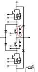
it is just two of two-level half bridge converter with additional diodes connected between the DC link. So the DC link mid point is no longer virtual. Lets assume the switches from top tp bottom as S1, S2, S3, S4. then, S1 and S3 makes one half bridge VSI (For positive side AC voltage) and S2 and S4 makes another VSI (For negative side AC output). the output terminal is between S2 ande S3. I hope this wil help....
This site uses cookies to help personalise content, tailor your experience and to keep you logged in if you register.
By continuing to use this site, you are consenting to our use of cookies.
") Thanks in advance!
Thanks in advance!