Continue to Site

Welcome to EDAboard.com

Welcome to our site! EDAboard.com is an international Electronics Discussion Forum focused on EDA software, circuits, schematics, books, theory, papers, asic, pld, 8051, DSP, Network, RF, Analog Design, PCB, Service Manuals... and a whole lot more! To participate you need to register. Registration is free. Click here to register now.

URGENT : Group Delay Chebyshev Filter

Status
Not open for further replies.

Heidi.Eissa

Newbie level 4
Joined
Apr 30, 2010
Messages
6
Helped
0
Reputation
0
Reaction score
0
Trophy points
1,281
Activity points
1,320
I'm designing an analog chebyshev filter of order =10 and i want to know the formula of group delay , i know it's -1*derivative of phase of frequency response but i wonder if there is a clearer formula for the chebyshev filter relating the group delay with the filter order .. if you know i'd be very thankful for your help !

thank ! :)
 

I don't know, if the formula that is available will be "clearer", but I can give you some background information to that expression.
There are in principle two alternatives:
1.) You can split the 10th order function into 5 separat transfer functions - each of 2nd order. For each of this functions you can use a delay formula that is available (expressed in terms of pole frequency and damping resp. pole Q). The final delay function then is the sum of the 5 delay functions.
2.) There is another formula based on the pole location of the 5 pole pairs. Thus, the delay formula consists of the sum of 5 expressions - each containing the real part of the respective pole and the squared magnitude of the difference (w-Sn), with Sn=pole location.
______________
As you will see, it's relatively complicated and I doubt if it really helps.
Nevertheless, if you are interested I can give you details (tell me if to 1) or 2)).

LvW
 
I don't know, if the formula that is available will be "clearer", but I can give you some background information to that expression.
There are in principle two alternatives:
1.) You can split the 10th order function into 5 separat transfer functions - each of 2nd order. For each of this functions you can use a delay formula that is available (expressed in terms of pole frequency and damping resp. pole Q). The final delay function then is the sum of the 5 delay functions.
2.) There is another formula based on the pole location of the 5 pole pairs. Thus, the delay formula consists of the sum of 5 expressions - each containing the real part of the respective pole and the squared magnitude of the difference (w-Sn), with Sn=pole location.

As you will see, it's relatively complicated and I doubt if it really helps.
Nevertheless, if you are interested I can give you details (tell me if to 1) or 2)).

LvW


______________


thank you so much for your quick reply :) .. dunno , i feel that the first one is less complicated , so can you provide me with more details about it ? :)
 

OK, see the attachement for details.
Remember, at first you have to split the transfer functions into sepate bandpass functions Hi - each of 2nd order (of course).
Then you have to follow the group delay definition and to sum all components.
But I am afraid, it is a rather cumbersome procedure.
Good luck.
LvW
 

Attachments

  • Group delay band pass.pdf
    60.6 KB · Views: 94

Sorry, I just have realized that I have mixed your posting with another posting dealing with a high-order bandpass.
In your case, it is a lowpass - that's a bit more easy. Wait some minutes for my revised pdf-attachement.
LvW
 
Last edited:

See the attachement for the low pass case.
I hope there is no typing error.
Regards

CORRECTION (typing error) : In the pdf-attachement, the last expression (group delay of a standard 2nd order lowpass) has to be multiplied by 1/wp
 

Attachments

  • Group delay low pass.pdf
    63 KB · Views: 86
Last edited:

See the attachement for the low pass case.
I hope there is no typing error.
Regards

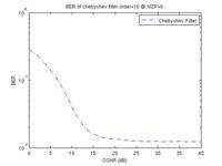
thank you so much .. but i have another question now 'if u don't mind :$' when i plot the BER versus the OSNR for the chebyshev low pass filter of order =10 , when i use number of zero padding subcarriers=0 'since i'm using this filter in coherent optical OFDM system' and i found it don't decrease smoothly .. so can you tell me if you know why is that happening ?


thanks : )
 

Sorry, I can't. Perhaps another forum member has corresponding experience?
 

Hi Heidi,

there was a typing error in the pdf-attachement and I have corrected it, see my posting yesterday 14:11.
I am sorry.
LvW
 

Status
Not open for further replies.

Similar threads

Part and Inventory Search

Welcome to EDABoard.com

Sponsor

Back
Top