Continue to Site

Welcome to EDAboard.com

Welcome to our site! EDAboard.com is an international Electronics Discussion Forum focused on EDA software, circuits, schematics, books, theory, papers, asic, pld, 8051, DSP, Network, RF, Analog Design, PCB, Service Manuals... and a whole lot more! To participate you need to register. Registration is free. Click here to register now.

ultrasonic cleaning transducer resonance frequency

Status
Not open for further replies.

xeratule

Member level 4
Joined
Apr 4, 2009
Messages
69
Helped
1
Reputation
2
Reaction score
1
Trophy points
1,288
Location
Istanbul / TURKIYE
Activity points
1,975
Hi all,

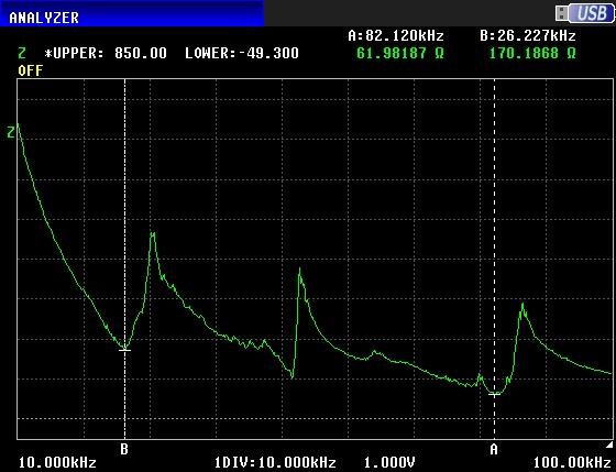
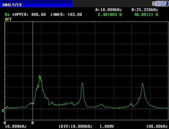
I have ultrasonic cleaning transducer and I can measure its impedance with an impedance analyzer. Please correct me if I'm wrong from now on then:

The resonance frequency is the frequency where its impedance is minimum. So when I apply various loads to the transducer, its resonance frequency shifts between 25khz - 30kHz. As the transducer is a piezoelectric crystal, its impedance has both active and reactive components (Z = R -jX). I try to get most active power from the transducer while power factor will not be less than 0.9. Lets say at frequency f1 the transducer has minimum impedance Z1 = R1 - jX1 . And at f2 it has minimum real impedance Z2 = R2 - jX2.

Here we have Z1 < Z2 and R2 < R1. If I match X1 and X2 with their complex conjugates ( ex: add series inductor) , that would result in: Z1 = R1-X1+X1 = R1 and Z2 = R2-X2+X2 = R2. This will make Z2 < Z1. As impedance is smaller, more current can pass through it. So can I have more active power where transducer operates better at f2 instead of f1? Or does it still operate better at its self resonance frequency f1 and not resonate well at f2?

Would like to have your valuable answers soon, thanks in advance.

Erhan
 

I would expect an impedance something like this:


You want to use the frequency with the lowest real part. In my diagram it is at M3.

I am surprised by your wide variation in resonant frequency - I normally see fairly small variations with load (<1kHz) - it is the Q that varies. Is the piezo bonded on to a plate?

Keith.
 
I used to test the electronics for ultra sonic cleaners. We just drove the crystal really hard (>50W?) and did not bother tunning the set against the transducer because they might (would?) get separated in use use and mixed up with other sets. If you are really worried, how about using the transducer itself to determine the operating frequency? use lots of loop gain and a small impedance in the earthy end of the transducer and a wide band transformer to match from your PA to the impedance of the transducer at resonance.
Frank
 
The resonance frqeuency shift depends much on the transducer design. The simple US cleaner standard design, where a piezo disc performs bending vibrations will be most likely stronger affected by load variations, e.g. liquid level.

As the diagram posted by Keith illustrates, you get a pairs of series and parallel resonances. Typically the low impedance series resonance is ultilized. I didn't exactly understand your impedance considerations. If you are able to tune the generator or have a free running design, you don't need to match a complex impedance. In any case, the fundamental wave can be expected to give the largest mechanical output.
 
Dear Keith,
I am surprised by your wide variation in resonant frequency - I normally see fairly small variations with load (<1kHz) - it is the Q that varies. Is the piezo bonded on to a plate?
Keith.
As FvM mentioned, the resonance frequency shifts much with different liquid levels and also with different tempratures. (And yes the transducers are bounded under a caldron) I have Z impedance garph of the transducer (loaded) something like your graph. But series real impedance graph (Rs) is different. Please see the attached files. I try to use the series resonance frequency which is close to 25khz.


Dear Frank,
I actually didn't understand your solution. I don't have PA circuit to match with transducer. I just try to match transducers impedance with transformer winding in order to prevent reactive power.

Dear FvM,
I didn't exactly understand your impedance considerations. If you are able to tune the generator or have a free running design, you don't need to match a complex impedance. In any case, the fundamental wave can be expected to give the largest mechanical output.

I try to get largest mechanical output but don't want to loose power for reactive component of the transducer impedance. Thats why I try to match its complex part (capacitive) with transformer (inductive).

So should I choose my operating frequency to Zmin or Rsmin? And I am going to adjust transformer matching windings to that point.

Thanks,

Erhan
 

I think first concern here should be efficiency of the electromechanical power conversion. You should choose your operating frequencies where transducers work as efficiently as possible. How you determine those frequencies depends on you and your equipment. I use two transducers, one transmits and the other receives, I monitor received power while sweeping the transmitter's frequency.
You may have a look up table storing best op. frequencies under different load conditions(or you may have linear relationship that you can formulate).
Then, you can consider reactive power compensation issues. I dont know wheter one L value compensates enough for your whole operating range. You may try to find an optimum value for the L or you may have a few L s to adaptively combine in accordance with op. frequency.
 
  • Like
Reactions: FvM

    FvM

    Points: 2
    Helpful Answer Positive Rating
if the right trace actually shows Rs, it would be rather untypical for an ultrasonic transducer. All measurements I know are showing a distinct minimum in real impedance part. The usual equivalent circuit however suggests to model the static transducer capacitance as a parallel rather than a series element.

I wonder, if the curve actually shows an untypical tranducer impedance or a problem with the measurement?

I was saying, that a transducer can be operated without a matching circuit at it's series resonance frequency.

Particularly for low Q transducers inductive tuning can be reasonable. You get a real input impedance with a parallel inductor at the series resonance or a series inductor at the parallel resonance frequency. But if the transducer resonance is shifting, the tuning can be only a compromise.
 
Dear Fvm,
That measurement is the Rs measurement of the impedance analyzer and won't be wrong if positive and negative sections of the transducer are the probe connection places.
I was saying, that a transducer can be operated without a matching circuit at it's series resonance frequency.
As Q (X/R = reactance/resistance) is low and variable for the system (because resonance frequency shits) I think I need to use matching circuit and also aim to follow resonance frequency actively. So should I operate at Zmin?

Dear ferdem,
... you can consider reactive power compensation issues. I dont know wheter one L value compensates enough for your whole operating range. You may try to find an optimum value for the L or you may have a few L s to adaptively combine in accordance with op. frequency.
I aim to have a constant optimum L value which will offer enough efficiency and good mechanical power from the transducer.
 

That measurement is the Rs measurement of the impedance analyzer and won't be wrong if positive and negative sections of the transducer are the probe connection places.
This should be expected at least. I would prefer to see a Z or Y locus plot, to verify á consistent measurement.
 
Last edited:

I would prefer to see a Z or Y locus plot, to verify á consistent measurement.

What is locus Z or Y plot, could you explain or show a sample plot? Maybe I can have it and post it for you then.

I was saying, that a transducer can be operated without a matching circuit at it's series resonance frequency.

Particularly for low Q transducers inductive tuning can be reasonable. You get a real input impedance with a parallel inductor at the series resonance or a series inductor at the parallel resonance frequency. But if the transducer resonance is shifting, the tuning can be only a compromise.

If I don't use matching circuit I get very low mechanical output although I operate at series resonance frequency. But if I connect a parallel inductor I can get sensibly higher output power. I think that's because of the low Q of my transducer as FvM stated before.

One more think I want to get informed about: I use transformer secondery winding as parallel inductor for the transducer. Transformer primary is connected to the driver and supply circuit. The impedance at transformer's secondary effects its primary impedance too. So how can I adjust the number of turns at primary? What is the relation of secondary winding impedance and primary winding impedance when the transformer is loaded? :???:
 
Last edited:

I append piezo transducer impedance diagrams from a Valvo/Philips application book (in German). I would expect, that your impedance analyzer software supports a similar plot.

Transformer inductance can be utilized for impedance matching, of course. But you should consider, that it has both series (leak) inductance and parallel (main) inductance. With an ungapped core transformer, I would expect the series inductance to be the dominant component.
 

Attachments

  • Piezo impedance root locus plot.pdf
    27.3 KB · Views: 225

Status
Not open for further replies.

Similar threads

Part and Inventory Search

Welcome to EDABoard.com

Sponsor

Back
Top