Continue to Site

Welcome to EDAboard.com

Welcome to our site! EDAboard.com is an international Electronics Discussion Forum focused on EDA software, circuits, schematics, books, theory, papers, asic, pld, 8051, DSP, Network, RF, Analog Design, PCB, Service Manuals... and a whole lot more! To participate you need to register. Registration is free. Click here to register now.

understand a dynamical braking system

Status
Not open for further replies.

electricboy

Newbie level 6
Joined
Apr 12, 2011
Messages
13
Helped
0
Reputation
0
Reaction score
0
Trophy points
1,281
Activity points
1,379
Hi,

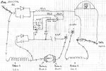
I finally found a way to brake dynamically a drill and i found it on a circular saw.
I've drawn the electrical scheme of its brake which work with the drill (both the coils and the rotor are the universal motor).
The problem is that I want to resize the componant to make it brake faster.But I dont fully understand of this brake work.

Can anybody enlight me?
 

Attachments

  • img001.jpg
    img001.jpg
    1.1 MB · Views: 58

I am not able to read your diagram very well. To brake a universal motor, there are two ways, one is to inject low voltage DC into the motor*, the other is to put a low value resistor (or a short) across the motor. I think your is the first type.
* typically 230V ac motor has 12V DC braking (same current or you burn out the windings).
Frank
 

Thank you for your answer Chuckey!
This is what I've had understood about this circuit.
When you close the switch the number 3 and 4 are connected then the current flows in the coil 2 and it works.And when the switch is open again, 3 and 4 disconnected, that cut the current and the 2.2µF capacitor put his current in the motor by the brush 2.


The problem is that I don't understand the midle part of the circuit why is there a Mosfet with the capacitor and a thyristor? And why they made a rectifier (if I not wrong) in both the part of the circuit?
 

I doubt, that the circuit is correct (respectively complete). The capacitor will prevent an armature DC current, thus I can't see a braking action.
 

Hi FvM,
And if the polarity of the capacitor is inversed (because i'm not sure of his sens) would you see a braking action?
this diagram is the circuit that I have verify a couple of times so i Think that everythings is there and when
I tried a lot of time there 's really a braking action (instead of 4 or 5 sec the motor takes 1 to 2 sec to brake with it.)
But the assumption with the current flow may be wrong ...

---------- Post added at 11:30 ---------- Previous post was at 10:17 ----------

Sorry I just have found that the capacitor in derivation with the diodes are varistors
 

Status
Not open for further replies.

Similar threads

Part and Inventory Search

Welcome to EDABoard.com

Sponsor

Back
Top