Continue to Site

Welcome to EDAboard.com

Welcome to our site! EDAboard.com is an international Electronics Discussion Forum focused on EDA software, circuits, schematics, books, theory, papers, asic, pld, 8051, DSP, Network, RF, Analog Design, PCB, Service Manuals... and a whole lot more! To participate you need to register. Registration is free. Click here to register now.

[SOLVED] AT89c55 Connection with ULN2803/4

Status
Not open for further replies.

TopGunPk

Newbie level 2
Joined
May 17, 2009
Messages
2
Helped
0
Reputation
0
Reaction score
0
Trophy points
1,281
Activity points
1,308
Hi.

This might be faced by some people and there might be answers, but i have yet to find.

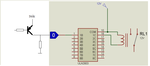
I have connected a ULN2803/4 chip with a AT89c55 controller Port-2 (TTL output port). The ULN is supposed to drive 12V relays, that have one of the coil legs connected to 12V and the other leg connected to the ULN.

Since ULN is TTL compatible, writing a logic "1" to the respective port pin, and hence the ULN input, turns ON the relay and a logic "0" turns it off. So far so good.

The problem i am facing is, at startup all relays turn ON, untill the INIT piece of code executes to put all port pins to Logic "0" state. The problem is that the controller pins are internally pulled-up, hence when the power is turned on, while the controller is still in reset stage, the port pins are all at logic "1", and the relays turn ON.

This is creating problems for me, as the relays are supposed to drive critical Contactors which are driving a Star-Delta 15KW motor. If all the contactors turn ON at power up (MAIN, STAR, DELTA), then there would be a blast in teh motor, OR the Overload will trip.

Any suggestion how i can keep teh ULN outputs OFF at power up, and ONLY turn the ULN ON when needed ? Would a Pull-to-Ground resistor on ULN inputs solve the problem ? If so, what value ?

Zeeshan
 

That's the issue with all 8051-derivatives, and there is no simple fix for it ..
You'll have to re-design your circuit and change positive-logic (active=1) to negative logic (active=0) ..
One option is to use an optocoupler and connect the diode (with resistor) between microcontroller's pin and +Vcc ..
Then the output can be used to dive ULN or discrete transistor and RLY ..


IanP
:wink:
 

I also faced the same problem... I changed the logic from positive to negative.. That time i was facing one problem... Relay coil one end is connected to 12V and another end is connected to ULN output.. When i give '1' [HIGH] from controller to ULN then ULN switch ON the relay.. Due to above said problem i changed the logic.. These time Relay coil one end is connected to GND and another end is connected to ULN output.. When i give '0' [LOW] from controller to ULN then ULN doesn't switching on the Relay... Can any body tell the reason why is it so??
 

Relay coil one end is connected to GND and another end is connected to ULN output.. When i give '0' [LOW] from controller to ULN then ULN doesn't switching on the Relay... Can any body tell the reason why is it so??
The ULN's outputs are Open-Collector, they can only work with loads connected to +Vc ..
Add PNP transistor, change program to use negative logic and off you go - see attached picture ..

IanP
:wink:
 

Attachments

  • uC - to - PNP - ULN2803 driving a relay.png
    uC - to - PNP - ULN2803 driving a relay.png
    80.3 KB · Views: 166

I also faced the same problem... I changed the logic from positive to negative.. That time i was facing one problem... Relay coil one end is connected to 12V and another end is connected to ULN output.. When i give '1' [HIGH] from controller to ULN then ULN switch ON the relay.. Due to above said problem i changed the logic.. These time Relay coil one end is connected to GND and another end is connected to ULN output.. When i give '0' [LOW] from controller to ULN then ULN doesn't switching on the Relay... Can any body tell the reason why is it so??

the reason is simple ULN's are open Collector output so they are used to sink current ( i.e provide ground when active) rather than source current (i.e provide high voltage when active). so you have to reverse the logic at ULN's input side not output side...
 

Suppose i want to drive 8 relays means is it required to put 8 PNP transistor [between controller o/p and ULN i/p] or is there any other way...
 

Dear my friend

it is a famous 8051 problem because at reset phase of the controller all output are high ... then you can add an inverter between the controller output and ULN and active what you need by LOW it's output

Best Regards

MedTronic
 

Hi IanP.

Thanks. Yes i had to (eventually) change thr circuit. couldnt do much as the PCB was already made, but i added an optocoupler driven by teh 8051 port pin (with a series resistor 330 Ohm) and the NPN transistor in teh opto provided the GND for teh PNP transistor sourcing 12V to teh relay.

So now, one leg of all relys are connected to Ground, and teh other leg of each relay goes to a respective PNP transistor, being driven by an opto (TLP521-4).

Thanks again guys.

Regards,
Zeeshan
 

Status
Not open for further replies.

Similar threads

Part and Inventory Search

Welcome to EDABoard.com

Sponsor

Back
Top