Continue to Site

Welcome to EDAboard.com

Welcome to our site! EDAboard.com is an international Electronics Discussion Forum focused on EDA software, circuits, schematics, books, theory, papers, asic, pld, 8051, DSP, Network, RF, Analog Design, PCB, Service Manuals... and a whole lot more! To participate you need to register. Registration is free. Click here to register now.

Why Super source follower AC response shows it have a pair of conjugate poles?

Status
Not open for further replies.

dominoeff

Junior Member level 1
Joined
May 6, 2010
Messages
17
Helped
0
Reputation
0
Reaction score
0
Trophy points
1,281
Location
china-mainland
Activity points
1,413
Hi guys:
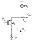
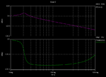
I am using a super source follower to enhance my driver's slew rate.but it cause my circuit oscilation,AC simulation shows the super source follwer gave conjugate poles,by my analysis,it get two polses but should not be conjugate poles ,could anyone explains this for me!
 

It`s hard to answer because we don`t know which models (accuracy/reality) your hand analysis are based on.
On the other hand, because of 100% feedback it is no surprise that the source follower (simulation with real FET models) exhibits a complex pole pair.
 

It`s hard to answer because we don`t know which models (accuracy/reality) your hand analysis are based on.
On the other hand, because of 100% feedback it is no surprise that the source follower (simulation with real FET models) exhibits a complex pole pair.

Thanks LvW,
The source follwer circuit is attached , and the 2rd picture is the AC simulation result by hspice.

I just using MOSFET small signal model to analyse the circuit.I can only find two real poles at the gate of M2 and Vout respectively. I want know why it is complex, and that maybe the reason cause my circuit oscillation.

I am not sure how to use feedback theory to analyse this circuit.
Thank you.
 

Attachments

  • SSF.png
    SSF.png
    11.6 KB · Views: 1,383
  • bode plot.png
    bode plot.png
    14.3 KB · Views: 457

I can only find two real poles.
It's two real poles with a simplified FET model (not considering internal resistances and terminal inductances). But adding feedback turns it into a complex pole pair. Also a feedforward zero can be seen from the phase diagram.

It's of course possible to determine an exact feedback factor for the circuit. But it's a bit complicated, because M1 is loading the output with the input impedance of a common gate amplifier.

Thanks FvM,
If I understood correctly,it's a 100% feedback by M1. If we open the loop at source of M1, the circuit is a two stage amplifer, two common source amplifer stage.Now we connect the Vout to M1 source ,the equal input voltage is Vin-Vout,which means the feedback factor is 1.So now the two stage amplifer works as a unit gain buffer,or source follower.The close loop gain is Av_o/(1+fAv_o),f=1,and this expression explains why 2 real poles changed into a complex pair?
Thanks & Regards
dominoeff
 

dominoeff,
With enough loop gain, any two real poles can become complex conjugate poles and can even move to the right half of the plane. In your case, the open loop poles are real poles and they become complex due to the large loop gain, try sketching root-locus plot of a simple two negative real poles open loop system on unity gain feedback to understand this.
Thanks saro_k_82,
Now i know something about how this happen,but there is still something confuse me . Why i can't find this by using small signal model of FET .For the considered frequency is not very high the terminal inductance is ignored like FvM said.But i think this should not be the reason why i get a wrong transfer function.
Thanks & Regards
dominoeff
 
Last edited:

............................
But i think this should not be the reason why i get a wrong transfer function.
Thanks & Regards
dominoeff

In which case you get a "wrong transfer function" ? Simulation result or outcome of theoretical calculations ?
What really is the problem? To understand WHY the poles are complex ?
One remark - as far as ac simulation runs are concerned: You must not blindly trust ac simulations. Even in case of instability the magnitude response may show only a small peaking. What about the rising of the phase characteristic in your BODE diagram? You should extend the simulation to higher frequencies (at least one decade).
 

But i think this should not be the reason why i get a wrong transfer function.
No, as said, you'll get a complex pole pair already with a simple FET model. But you didn't show your calculated closed loop transfer function, so we can't know if or why it's wrong.
 

Status
Not open for further replies.

Similar threads

Part and Inventory Search

Welcome to EDABoard.com

Sponsor

Back
Top