Continue to Site

Welcome to EDAboard.com

Welcome to our site! EDAboard.com is an international Electronics Discussion Forum focused on EDA software, circuits, schematics, books, theory, papers, asic, pld, 8051, DSP, Network, RF, Analog Design, PCB, Service Manuals... and a whole lot more! To participate you need to register. Registration is free. Click here to register now.

PIC16F628A and flashing led with input

Status
Not open for further replies.

vaka85

Advanced Member level 4
Joined
May 9, 2008
Messages
100
Helped
0
Reputation
0
Reaction score
0
Trophy points
1,296
Activity points
2,112
Hi all,

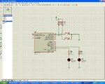
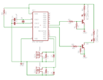
I'm a beginner in pic programming, and I'd like to blink a led (a fast flash) everytime there is an input (a piezo buzzer connected in the pic inputs).
Here is the code, I'm using mikroc:

Code:
#include "16f628a.h"

void main(void) {
    // set portA as inputs
    TRISA = 1;
    // set portB as outputs
    TRISB = 0;

 for(;;)         // forever
       {

       if (PORTA.f0)      // if there's a trigger pulse
       {
          PORTB.f0 = 1;     // turn the LED on
          Delay_ms(100) ;         // wait 100 ms
          PORTB.f0 = 0;   // turn led off
       }
       if (PORTA.f1)      // if there's a trigger pulse
       {
          PORTB.f1 = 1;     // turn the LED on
          Delay_ms(100) ;         // wait 100 ms
          PORTB.f1 = 0;   // turn led off
       }
       }
}

The output part should be fine, because I've used it in another project... but the input one?
I've checked with an oscilloscope and the external trigger is ok..

Could you tell me where I'm wrong?

Thanks
 

you are in an endless loop so in addition to a delay after turning the LED on you need a delay after turning it off otherwise it appears to be on all the time a button is pressed, e.g
Code:
       if (PORTA.f0)      // if there's a trigger pulse
       {
          PORTB.f0 = 1;     // turn the LED on
          Delay_ms(100) ;         // wait 100 ms
          PORTB.f0 = 0;   // turn led off
          Delay_ms(100) ;         // wait 100 ms
       }
 

ah.. I understand...

but the led doesn't even turn on!
 

what complier are you using ?
for the following I used the Hi-Tech compiler for a PIC16F917 on the Microchip Mechatronics board
Code:
        TRISA1=1;                 // RA1 is switch input
        TRISD6=0;                 // RD6 is LED output
        TRISD5=0;                 // RD5 is LED output
        RD6=1;                    // set LED
        while(1)
               {
                RD5=RA1;                                // copy sw2 to LED
                RD6=!RD6;                               // invert LED to blink it
                // check for received character and echo it 
                while(uartReceived()) putchar(getchar());
                tenthsSecondDelay(10);                  // delay for a second
                }
}
 

I'm using mikroC compiler...
sorry but I don't understand what your code has to do with my problem :)

I'm not sure if the input part of my code is ok... in you opinion it's ok?
Code:
if (PORTA.f0)
 

in Hi-Tech the switch test would be
Code:
   if(RA1)
      {
never used microc so don't know the syntax
 

Hello
TRy this code it works in MikroC


void main() {
CMCON = 0x07;

//ANSEL = 0x01;
//ADCON1=0b00000110;
TRISA = 0b01100111;

//TRISA=255;
TRISB=0b00000000;
//RA0 input

//RA1 input 2
//RB4 output
//RB5 output 2
while(1)
{


if(RA0_bit==0)
{
RB4_bit=1;
Delay_ms(1000);
RB4_bit=0;


}


if(RA1_bit==0)
{


RB5_bit=1;
Delay_ms(1000);
RB5_bit=0;

}

}

}
 

Attachments

  • circuit.JPG
    circuit.JPG
    195.8 KB · Views: 161

i made the delay for 1 sec
Delay_ms(1000) // 1000ms = 1sec>>> you can change it as required
 

Hi vaka85;

Here is your code but modified and commented by me. Try it out:

Code:
#include "16f628a.h"

void main(void) {
[COLOR="red"]    CMCON = 0x07; // switch off comparators; it is a must to use porta for input[/COLOR]
    // set portA as inputs
    TRISA = [COLOR="red"]3; // bin 11, NOT 1 !!; set porta.0 [B]AND porta.1[/B] as inputs,[/COLOR]   
    // set portB as outputs
    TRISB = 0;
    [COLOR="red"]PORTB = 0; init portb, all leds off at start[/COLOR]

   for(;;) {        // forever 
      if (PORTA.f0) {     // if there's a trigger pulse [COLOR="red"]on porta.0[/COLOR]
          PORTB.f0 = 1;     // turn the LED on
          Delay_ms(100) ;         // wait 100 ms
          PORTB.f0 = 0;   // turn led off
      }
      if (PORTA.f1) {     // if there's an trigger pulse [COLOR="red"]on porta.1[/COLOR]
          PORTB.f1 = 1;     // turn the LED on
          Delay_ms(100) ;         // wait 100 ms
          PORTB.f1 = 0;   // turn led off
      }
   }
}

And see also the first post by horace1 above (but the additional delay doesn't really necessary)

Ooops:
What's this mean?
"a piezo buzzer connected in the pic inputs"
Do you using the piezo buzzer as a microphone? Interesting... does it working? What's about the voltage levels?

Your program works with HIGH active pushbuttons as input triggers, or modify the IFs like this
if (PORTA.f0 == 0) { // if there's a trigger pulse
 
Last edited:
  • Like
Reactions: vaka85

    vaka85

    Points: 2
    Helpful Answer Positive Rating
thank you very much guys.
I'll try your suggestions in the next days, and then I'll let you know how it works!

EDIT: sorry, I've forgotten to reply to zuisti question..
I use the piezo on my drum. It "detects" the hits on the drum, and those are the inputs. The voltage obviously depends on the power of the hit, but it's about 2-3 V..
 
Last edited:

I've tried both suggestions, but they don't work.

Or at least, they work a little :)

in particular, the one posted by zuisti: the led turns on, but it keeps blinking on and off forever... I don't understand why, because there is the command
Code:
PORTB.f0 = 0;   // turn led off

I've tried with
Code:
break;
but obviously it "powers off" all the system after the first hit..

any idea?

Thanks
 

What is your input circuit exactly?
Just an idea: apply a big "pull-down" resistor on each input pins (for ex. 1 MOhm to the GND).
 

yes, sorry, I've forgotten to post the schematic.
Here it is
(attached)

zener diodes are for protection, but I don't think they are real necessary..
 

Attachments

  • schematic.png
    schematic.png
    50.5 KB · Views: 141

It may be the inputs are too sensitive or you get a noise (a feedback from the power leds?) ...
Idea:
Decrease the values of R2 and R5 step by step (first, say, to 220k).
Without any voice (no trigger) the leds must be off !!

And ... keep the zener diodes (for safety).
 

thank you for your help..

The schematic I've posted is the "final" one, but I'm trying the pic with a more basic one.. Only the piezo connected directly to the pic inputs. So there aren't R2 and R5... I don't know..
With the oscilloscope I've checked all the signals, and the pulse arrives correctly to the pic input...

Maybe there is some problem with my old pic programmer... MikroC compiles the software without errors, and also ICProg (the software to program the pic) doesn't show any error..
At this point I'll try with a new programmer that I've just bought, I only have to wait for the international shipping :)
 

OK, good luck!

Two things yet:

- your scope HAS an 1M input resistance ...

-This task is an example of what must be resolved using interrupts .
Now, while the long wait (Delay_ms xx) runs, the system is insensitive to the inputs..

Bye
 

OK, good luck!
thank you ;)

- your scope HAS an 1M input resistance ...

Yes, but if I can see on the scope the 2 V pulse, also the pic sees AT LEAST the 2 V pulse. Doesn't it?

This task is an example of what must be resolved using interrupts .
yes, you're right... Infact the actual mode isn't so "efficient", particularly when the hits on the drum are very fast...
I'm not so good in programming... I'll study how to implement interrupt mode and then I'll post my try :)

thank you very much
 

finally I have some free time and I'm on this project.
Now it works (in the simulator, I don't know yet if it works also in the real world :) ).. I changed the line
TRISA = 3;
in
TRISA = 0xFF;

now I'd like to improve the circuit... 2 questions:

- if I want to use interrupts, and want to manage 4 input drums, is it possible? I mean, I've read that I can use only 1 or 2 inputs as trigger inputs...
- could I control the duration of the output "high level" with an external trimmer? Is it correct if I read the ADC with the command read_adc() ? The adc inputs are RA0/AN0 or RA1/AN1?

Thanks
 

the PIC16F628A only has two timers - I would suggest you move to a more powerful processor
for this type of work I would use a dsPIC - very good to connect to midi systemd
 

Status
Not open for further replies.

Similar threads

Part and Inventory Search

Welcome to EDABoard.com

Sponsor

Back
Top