nima_1981
Member level 3
- Joined
- Apr 22, 2010
- Messages
- 61
- Helped
- 0
- Reputation
- 0
- Reaction score
- 0
- Trophy points
- 1,286
- Location
- Ocean Mind
- Activity points
- 1,877
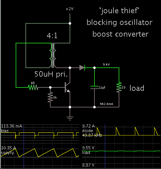
DC-DC converter 1V to 5V
Hi ,
I'm new in this forum , and in the fist relay sorry for my English writing .
i need Dc-dc Converter 1v To 5v but i can not use any chip for this problem , any one can help me ?
Hi ,
I'm new in this forum , and in the fist relay sorry for my English writing .
i need Dc-dc Converter 1v To 5v but i can not use any chip for this problem , any one can help me ?