Continue to Site

Welcome to EDAboard.com

Welcome to our site! EDAboard.com is an international Electronics Discussion Forum focused on EDA software, circuits, schematics, books, theory, papers, asic, pld, 8051, DSP, Network, RF, Analog Design, PCB, Service Manuals... and a whole lot more! To participate you need to register. Registration is free. Click here to register now.

Using PNP transistor as a swichto drive a relay

Status
Not open for further replies.

snaku

Junior Member level 3
Joined
Oct 5, 2010
Messages
27
Helped
1
Reputation
2
Reaction score
1
Trophy points
1,293
Location
Bangalore
Activity points
1,448
Hi everyone,
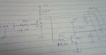
I have to drive a relay(which needs 5V and 30 mA) using a PNP transistor. I am giving 12 V to the transistor. I want 5v with 30 mA as output at the collector. How do I achieve this??? Please help me.
 

You can use a resistor is series with the load,
to calculate the value use

(12v-5v)/30ma=233 ohm

This is a resistor calculated to have a voltage drop of 7v @30mA,
if the current is lower then the output voltage will be higher,
if the current is higher then the voltage will be lower.

NOTE that this is suitable for leds, relays etc but not for digital chips that need 5v (mcu or ADC etc),
so if you want to feed any kind of chip use a 5v regulator.

Alex
 
  • Like
Reactions: snaku

    snaku

    Points: 2
    Helpful Answer Positive Rating
Hi Alex,
Thanks for ur quick reply.
I have desinged a circuit to change the polarity of the relay depending on LDR(light dependent resistor) output. I have attached the circuit image. Please let me know if it works.

Thanks
 

Attachments

  • relay.bmp
    839.8 KB · Views: 126

You are not using the LDR the way you should,
also in a transistor when the load is connected to the emitter then the output voltage
is always about 0.7v higher for PNP or 0.7v lower for NPN from the voltage of the base.

Take a look at Transistor Circuits
is has some good info and also a proper LDR circuit near the end of the page

Alex
 
  • Like
Reactions: snaku

    snaku

    Points: 2
    Helpful Answer Positive Rating
I have just shown the LDR as block diagram.It gives either 5V or 0V. So no issue with that. I had designed the same circuit using NPN transistor(Sorry for poor image).I have attached the circuit. When I tried to use PNP transistor I got confused. In my application, when I use PNP transistor, the load cannot be in series with the current limiting resistor on the collector side. Because two ends of the relay is connected to two different transistors.
How do I go about the design with PNP transistor?

Thanks
Naveen.
 

Attachments

  • relay_npn.JPG
    relay_npn.JPG
    11.9 KB · Views: 159

I don't see the need for the second transistor, why do you use it?

Now, about the voltage, the output of your transistor is from the emitter,
the emitter in the PNP will be Vbase+0.7v so for 5v it will be about 5.7v.

The main problem is that you can't turn off the PNP transistor using 0/5v to the base because
in both cases you have a Vbe voltage above 0.7v (12v-0v=12v or 12v-5v=7).

If you still want to do it with a PNP then you also have to use a NPN that drives that PNP (with 12v) so it can turn off

Alex
 
Last edited:

Sorry I have attached a circuit by mistake in the previous post,
you could use something like this

0-5v_pnp_relay.gif

The alternative would be with only one NPN transistor, but you want to do it with PNP.

Alex
 

I have used the second transistor because when one end of the relay is 5v the other end should be 0V and vice versa.So when one transistor acts as source, the other transistor acts as a sink and vice versa.

Thanks for your replies.

Naveen
 

I still don't understand the purpose of using transistors in both ends of the coil,
why do you want to be able to reverse the voltage of the coil?
You can connect one end to positive supply or gnd and drive the other side of the coil with a transistor,
see my example in my previous post.

Alex
 

Actually the output is given to a module which has a relay and an open close gate arrangement. The gate will be closed when the relay is fed with one polarity and it opens when the polarity is reversed. I actually do not know the internal details of that module. I am supposed to design based on the requirement I just now said.
And I had a PNP transistor with me, so I tried to design with that.
Thanks for your question.

Naveen
 

Ok you want an output that can be inverted but the 5v requirement is not clear,
using a resistor you will only have 5v @30ma, if the output is not a relay coil it could be damaged ,
maybe you should use an emitter follower that will have an output of 5v without any resistance.

Alex
 

I am clear that I am giving 5V @30mA to relay.
 

The only proper way I can think of to be able to invert the polarity is an H bridge with the resistor in series with the coil.
A simple H-Bridge design « PocketMagic

I don't think it is possible to invert the polarity with only 2 transistors.

Alex
 
  • Like
Reactions: snaku

    snaku

    Points: 2
    Helpful Answer Positive Rating
Ok...I should work on that..Thanks for your time and replies..:-D
 

Status
Not open for further replies.

Part and Inventory Search

Welcome to EDABoard.com

Sponsor

Back
Top