Continue to Site

Welcome to EDAboard.com

Welcome to our site! EDAboard.com is an international Electronics Discussion Forum focused on EDA software, circuits, schematics, books, theory, papers, asic, pld, 8051, DSP, Network, RF, Analog Design, PCB, Service Manuals... and a whole lot more! To participate you need to register. Registration is free. Click here to register now.

Music keyboard wire question

Status
Not open for further replies.

wanamaker

Newbie level 5
Joined
Mar 28, 2011
Messages
10
Helped
0
Reputation
0
Reaction score
0
Trophy points
1,281
Location
Minneapolis - MN
Activity points
1,371
Hi there. Quick history: I pulled the housing off of a couple of MIDI keyboards that are specifically designed to hook up to a personal computer, MIDI to USB. (I basically created my own housing so they'd fit my space better.)

Having said that, I ran into a problem - the circuit boards need to be positioned in an area that are too far for some wires to reach. Here's what they look like (see below):

A. Side view:
female2.jpg

B. Top view:
female1.jpg

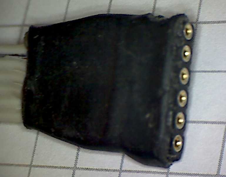
C. The area on the board the wire / cable plugs into (highlighted for clarity):
male.jpg


There's actually two questions:
1) What is this wire called? It's terrible that I ask a question about something I don't know the name of.
2) Since it cannot reach (to where I'd like it to go in relation to the keyboard), is there such a thing as an extension cord for this? That is, a male / female cord that I could extend this connection with?

Thanks for reading, any help would be appreciated!
 

Its called "Ribbon cable" - lots of individual wires running parallel to each other and with their insulation bonded into a flat ribbon.

Extending it is easy, just buy a matching plug and socket, a length of cable, crimp terminals and preferably a proper crimping tool. You have not told us where in the World you are so we can't advise you of a local supplier but the parts are standard and available from many sources. If you can't get the exact width of ribbon cable, get the next available one with more wires than you need and split away the unwanted ones.

Brian.
 
Brian, thanks for that!

I live in Minneapolis, MN. I know of one electronics store (AEI Electronics) but their reputation seems marginal from Google's reviews and I don't know of any others.

I think I'd like to make an extension cable for this. One of my biggest concerns is knowing what everything is called. After some research on the internet, it appears that I would need:

  • 14-way ribbon cable
  • 1 male and 1 female DIN 41612 connector
Does that sound right?

The things I'm not sure about would be what type of DIN connector (I think type C, but some images have me believe that D is it. I'm not sure. I'm just matching it to images by eye). Also, not sure how exactly the connections would attach to the ribbon cable. You mentioned crimping which sounds great. I'd like to avoid soldering if possible, but I'm not afraid if I know what to do.

What would you suggest based on the above?
 

I doubt the connector is a DIN 41612, it looks too small to meet that standard.

Very carefully measure the spacing between the holes in the plug, measure across say 10 holes and divide the result to be more accurate. Unfortunately they are manufactured in many different but similar sizes so looking at catalog pictures doesn't really help. When you have the spacing (the 'pitch') search one of the bigger electronic suppliers web pages, I suggest Farnell or Newark Electronics and find a match. I just checked Farnell and they have more than 300 variations on that kind of connector although many are compatible with each other.

The connector comes in two parts, a shell and a terminal. The shell is the plastic part that holds everything together and the terminals are the metal inserts that clasp the wire at one end and make the pin connection at the other. The shells come in different sizes, it looks like you need a 14-way one, the terminals usually come in bags of 100, you use as many as needed and keep the rest for later.

Fitting the terminals is a bit tricky at first but after a few tries you get the hang of it. The wire end is first stripped of plastic for a few mm, the exact length will be in the catalog data, then you hold the metal terminal is the special pliers, poke the wire into the end of the terminal and squeeze hard. It should twist the 'wings' of the terminal so they fold over and into the wire strands to make a good electrical connection. A second pair of 'wings' fold over the end of the plastic insulation and give it mechanical strength. When all the terminals are fitted, they simply push into the hole in the shell where their shape makes them lock into place.

Brian.
 

I guess I don't even know what a DIN 41612 is. I was just matching it up through images.

It looks like the form of the connectors are what matter most. As long as it fits the connector on the end of the wires and the circuit board I would think it would be fine.

Maybe I'm reading too much into this. I managed to find a video of a fellow doing this very thing I'd like to do here. How far off am I to that?
 

The connectors look like a popular JST type, and it's surely not DIN 41612. As said, you should measure the contact spacing, I guess it's 0.1". The contacts are crimped however, you need a special tool for it.

P.S.: The JST connector series I meant is named XH (header) respectively XHP(receptable) and is available e.g. from Digikey. The contact spacing is metrical 2.5 mm rather than 0.1".
https://www.jst-mfg.com/product/pdf/eng/eXH.pdf

Check the datasheet dimensions, if it fits.
 
Last edited:

I'm assuming the special tool is just a ribbon cable connector crimper?
I managed to find several on the internet. If I'm not mistaken a couple examples are **broken link removed** and Here (?)
 

I'm assuming the special tool is just a ribbon cable connector crimper?
No, because XH isn't a usual IDC connector. If you look sharp at your photos, you'll notice the difference. The ribbon cable is actually split into single wires, that are crimped to individual contacts. JST if offering a WC-110 tool, that is very expensive, multiple 100$. You may be able to find a more economic crimp tools available at a really good electronics DIY store. At worst case, the contacts can be "crimped" with flat-nose pliers and soldered as a precaution.
 

If you look very closely with a magnifier at the various surfaces of the connector housing, often a manufacturer name or logo and a series number can be found. What you have may be compatible with Molex KK series.

For a simple extension, an IDC type connector is usually easiest to apply. If you choose to use individual open barrel crimp connections, Molex makes a versatile tool shown here: Digi-Key - WM9999-ND (Manufacturer - 63811-1000)

Have you checked with ABC Electronics in Minneapolis? Newark (Element 14) Electronics has a sales office in Minneapolis. Digikey is headquartered in Thief River Falls, MN, a couple hundred miles from you so an order would arrive quickly.
 

I'm using both types and can tell, that a KK header doesn't fit a XH terminal. The suggested digikey crimp tool looks like it's suitable at least for processing small quantities.
 

If you look very closely with a magnifier at the various surfaces of the connector housing, often a manufacturer name or logo and a series number can be found.
The side of the connection on the board reads "14 SF." I don't know what the SF stands for but I'm assuming the 14 refers to the number of pins.

Have you checked with ABC Electronics in Minneapolis? Newark (Element 14) Electronics has a sales office in Minneapolis. Digikey is headquartered in Thief River Falls, MN, a couple hundred miles from you so an order would arrive quickly.

I looked at ABC's website earlier, I searched for "ribbon cable" and it returned no results. I gave up after that.
As far as the other places, I'm running into the same problem that I had in the beginning; what to order. I've actually emailed my question (in a very concise, easy to follow letter) to 3 different companies that claim to have "all things electronic" and each one of them said they didn't know how to help me. There's one place I have yet to try, AEI Electronics here in town. They have mixed reviews from Google so, it could be a crap shoot.
 

The side of the connection on the board reads "14 SF."
Suggests that it isn't an original JST part, but could be a compatible second source. Did you check the dimensions with the JST datasheet?
 

The distance between pins are the same as the JST sheet from what I see. However what my connector has seems to be soldered. I'm not sure if I could get away with a crimping version for an extension cable or if it would only work with a soldering connection. I'm not sure what the difference would be so long as it has a solid connection at both ends.
 

I've never seen solder contacts for this type of connector. So the only possible explanation in my opinion is, that they have been soldered, because the manufacturer had no suitable tool. As I already mentioned, it's also an option for you.

Soldering of connectors is generally avoided in commercial production. It also brings a risk of breaking the wires near the solder joint.
 

Odd. The company that made the keyboard is M-Audio which is quite a large global company. They claim to be "a leading provider of digital audio and MIDI solutions for today's electronic musicians and audio professionals." I'm sure they can afford the proper tools if necessary.

Back to the issue, are these types of connections so strange and hard to figure out that I've managed to stump the entire electronics community? What I know thus far is that:
- they are 14-pin connectors with a 2.55mm pitch.
- 300v 14-way ribbon cable

If I went to an electronics store to ask for this in order to create an extension cord, would this be enough information for them to help me out?
 

My consideration about soldered contacts is just a guess. It would be clearer, if I could see the contact finish.
If I went to an electronics store to ask for this in order to create an extension cord, would this be enough information for them to help me out?
Extension cable means exactly pin header at one side and receptable at the other? I fear, the connector series has no option for cable pin headers, some improvisation would be needed anyway. In any case, the most critical point is to find a receptable housing that fits the PCB pin header. I expect, that only the original part or a compatible type will fit exactly.

If the pins have a standard size (mostly 1/40") and distance, there is however an option to use "naked" pin headers and contact stripes soldered directly to the cable. The solution is less robust, but should work inside an instrument.
 

You can always replace the connectors on the PCBs at both ends to match a connector and cable assembly of your choice instead of struggling to find components to match what you have. The XH series that FvM suggested looks right but the series is designed for board to board interconnections and thus has no free hanging housings to facilitate construction of an extension.
 

The best solution depends on both, application and available resources. The below picture illustrates my previous suggesting to solder standard pin and socket stripes to the cable:


In this case, it's a 2mm socket. The solder connection is protected with a rugged, adhesive shrink tube.
 

Or, if all else fails, remove the socket (pin end) from the board and solder a ribbon cable between it and the original board holes. Not very elegant but it works and you use the original plug and socket, only a short extra length of cable is needed.

Brian.
 

Status
Not open for further replies.

Part and Inventory Search

Welcome to EDABoard.com

Sponsor

Back
Top