Continue to Site

Welcome to EDAboard.com

Welcome to our site! EDAboard.com is an international Electronics Discussion Forum focused on EDA software, circuits, schematics, books, theory, papers, asic, pld, 8051, DSP, Network, RF, Analog Design, PCB, Service Manuals... and a whole lot more! To participate you need to register. Registration is free. Click here to register now.

How to simulate straight line inductor in HFSS

Status
Not open for further replies.

Julian18

Full Member level 3
Joined
Apr 9, 2007
Messages
167
Helped
5
Reputation
10
Reaction score
5
Trophy points
1,298
Activity points
2,389
Hi there:
I am sorry if this is a repeat of a common question, but I can find a way to simulate a simple straight line inductor that the results generated can be verified by empirical formula. the model is shown below and also attached to this topic.
27_1301236829.jpg

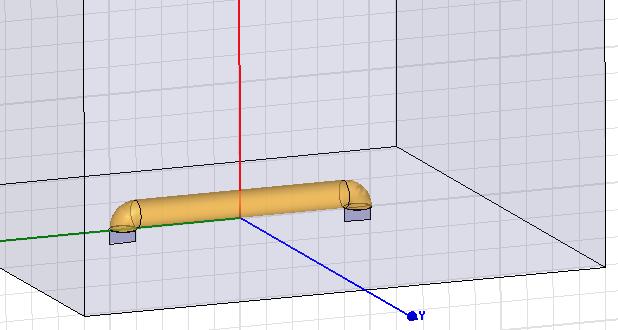
to be more specific, I use a PEC line with length=8mm & radius=0.5mm, the well known formula for straight line inductor is
ind(nH)=2*length*ln(2*radius/length-0.75)*10^(-7)​
which in this case gives inductance of 4.34nH;
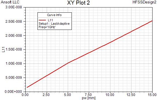
One the other hand, the simulation of HFSS model gives inductance of 2.57nH, which i think must be wrong.So the question is How to set HFSS model appropriately to get the right inductance?

Thanks

attachment is the HFSS model file.
 

Attachments

  • Straight_Line_Ind.rar
    31.1 KB · Views: 78

Oops, something wrong in the formula given above,
the line inductance is
ind(nH)=2*length*(ln(2*length/radius)-0.75)*10^(-7)​
 
Last edited:

You need to understand the effect of a conducting wall or ground plane on the value of inductance of a straight line. The formula you gave may only valid for free space. With a ground plane as close as you depicted from HFSS, I am not surprised the value is considerably lower.
 
You need to understand the effect of a conducting wall or ground plane on the value of inductance of a straight line. The formula you gave may only valid for free space. With a ground plane as close as you depicted from HFSS, I am not surprised the value is considerably lower.
Thanks Phytech,
I fact I have already thought of this effect, and simulated accordingly, but the inductance got enormous large as the figure below shown:
50_1301542931.jpg
There I increases the lower solve-space from 0.2mm to 15mm and you can see, things get messy. I think maybe the boundary conditions or lumped ports should be modified somehow, but I have no clue how to do to generate the acclaimed value the formula guarantees. BTW the I use Y(1,1) to get the inductance
Ind=im(1/Y(1,1))/2/pi/freq​


Best Regards
Julian
 

I cannot make an accurate comment without knowing exactly how you did the simulation. If you used the same configuration as picture above, then when you increase the lower space, you also increase the overall length of the line thus the value of inductance. Can you do the simulation with input and output ports from two ends and lift the line from the ground plane?
 

Status
Not open for further replies.

Part and Inventory Search

Welcome to EDABoard.com

Sponsor

Back
Top